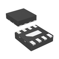
AMMP-5618-TR1 Avago Technologies US Inc., AMMP-5618-TR1 Datasheet - Page 2

AMMP-5618-TR1
Manufacturer Part Number
AMMP-5618-TR1
Description
IC AMP GP HI PWR 6-20GHZ 8-SMD
Manufacturer
Avago Technologies US Inc.
Datasheet
1.AMMP-5618-BLK.pdf
(9 pages)
Specifications of AMMP-5618-TR1
Gain
13dB
Current - Supply
107mA ~ 140mA
Frequency
6GHz ~ 20GHz
Noise Figure
4.4dB
P1db
19dBm
Package / Case
8-QFN
Rf Type
ISM, MMDS, WLL, 802.16/WiMAX, DBS, VSAT
Voltage - Supply
5V
Frequency Range
6GHz To 20GHz
Noise Figure Typ
4.4dB
Supply Current
107mA
Supply Voltage Range
5V
Rf Ic Case Style
SMD
No. Of Pins
8
Frequency Max
20GHz
Termination Type
SMD
Number Of Channels
1
Frequency (max)
20GHz
Operating Supply Voltage (typ)
5V
Package Type
SMD
Mounting
Surface Mount
Pin Count
8
Noise Figure (typ)
4.4dB
Filter Terminals
SMD
Rohs Compliant
Yes
Lead Free Status / RoHS Status
Lead free / RoHS Compliant
Test Frequency
-
Lead Free Status / Rohs Status
Compliant
Available stocks
Company
Part Number
Manufacturer
Quantity
Price
Part Number:
AMMP-5618-TR1
Manufacturer:
AVAGO/安华高
Quantity:
20 000
AMMP-5618 DC Specifications/Physical Properties
Symbol
I
θ
Notes:
1. Ambient operational temperature T
2. Channel-to-backside Thermal Resistance (T
RF Specifications
Symbol
Gain
NF
P
OIP3
RLin
RLout
Isol
Notes:
3. Small/Large -signal data measured in a fully de-embedded test fixture form T
4. Pre-assembly into package performance verified 100% on-wafer per AMMC-5618 published specifications
5. This final package part performance is verified by a functional test correlated to actual performance at one or more frequencies
6. Specifications are derived from measurements in a 50Ω test environment. Aspects of the amplifier performance may be improved over a more
2
d
-1dB
ch-b
ture (T
narrow bandwidth by application of additional conjugate, linearity, or low noise (Γopt) matching.
b
) = 25°C calculated from measured data.
Parameters and Test Conditions
Drain Supply Current (under any RF power drive and temperature) (V
Thermal Resistance
[3,4,6]
Parameters and Test Conditions
Small-signal Gain
Noise Figure into 50Ω
Output Power at 1 dB Gain Compression
Third Order Intercept Point;
∆f = 100 MHz; Pin = -20 dBm
Input Return Loss
Output Return Loss
Reverse Isolation
(T
A
= 25°C, V
d
= 5.0V, I
[2]
[5]
(Backside temperature, T
A
[5]
= 25°C unless otherwise noted.
d(Q)
= 107 mA, Z
channel
(T
c
) = 34°C) as measured using infrared microscopy. Thermal Resistance at backside tempera-
o
=50 Ω)
[1]
b
= 25°C)
Units
dB
dB
dBm
dBm
dB
dB
dB
A
= 25°C.
d
=5.0V)
Typ.
13
4.4
+19
+30
-12
-12
-40
Units
mA
°C/W
Sigma
0.4
0.2
0.9
1.2
0.7
0.6
1.2
Min.
Typ.
107
34
Max.
140


