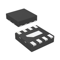
AMMP-5618-TR1 Avago Technologies US Inc., AMMP-5618-TR1 Datasheet - Page 7

AMMP-5618-TR1
Manufacturer Part Number
AMMP-5618-TR1
Description
IC AMP GP HI PWR 6-20GHZ 8-SMD
Manufacturer
Avago Technologies US Inc.
Datasheet
1.AMMP-5618-BLK.pdf
(9 pages)
Specifications of AMMP-5618-TR1
Gain
13dB
Current - Supply
107mA ~ 140mA
Frequency
6GHz ~ 20GHz
Noise Figure
4.4dB
P1db
19dBm
Package / Case
8-QFN
Rf Type
ISM, MMDS, WLL, 802.16/WiMAX, DBS, VSAT
Voltage - Supply
5V
Frequency Range
6GHz To 20GHz
Noise Figure Typ
4.4dB
Supply Current
107mA
Supply Voltage Range
5V
Rf Ic Case Style
SMD
No. Of Pins
8
Frequency Max
20GHz
Termination Type
SMD
Number Of Channels
1
Frequency (max)
20GHz
Operating Supply Voltage (typ)
5V
Package Type
SMD
Mounting
Surface Mount
Pin Count
8
Noise Figure (typ)
4.4dB
Filter Terminals
SMD
Rohs Compliant
Yes
Lead Free Status / RoHS Status
Lead free / RoHS Compliant
Test Frequency
-
Lead Free Status / Rohs Status
Compliant
Available stocks
Company
Part Number
Manufacturer
Quantity
Price
Part Number:
AMMP-5618-TR1
Manufacturer:
AVAGO/安华高
Quantity:
20 000
Figure 22. Outline Drawing.
Figure 23. Suggested PCB Material and Land Pattern.
7
0.126 [3.2]
.1260
Notes:
1. * Indicates Pin 1
2. Dimensions are in inches [millimeters]
3. All Grounds must be soldered to PCB RF Ground
Dimensional tolerance for back view: 0.002" [0.05 mm]
0.029 [0.75]
3.2
0.059 [1.5]
.0590
0.100 [2.54]
0.100 [2.54]
0.016 [0.40]
A
0.011 [0.28]
1.5
0.018 [0.46]
8
.0200
4
Symbol
AMMP
XXXX
YWWDNN
A
B
0.093 [2.36]
0.51
1
7
Front View
0.114 [2.9]
3 2 1
Back View
5
2 3
6 5
A
6 7
0.0685 (1.74)
0.198 (5.03)
.0180
.0110
Min
0.028 [0.70]
.0180
.0935
4
0.46
0.28
8
0.014 [0.365]
0.088 (2.25)
0.012 [0.30]
0.213 (5.4)
0.46
2.37
.0100
Max
0.016 [0.40]
Side View
B
0.25
Recommended SMT Attachment
The AMMP Packaged Devices are compatible with high
volume surface mount PCB assembly processes.
The PCB material and mounting pattern, as defined in the
data sheet, optimizes RF performance and is strongly rec-
ommended. An electronic drawing of the land pattern
is available upon request from Avago Sales & Application
Engineering.
Manual Assembly
1. Follow ESD precautions while handling packages.
2. Handling should be along the edges with tweezers.
3. Recommended attachment is conductive solder paste.
4. Apply solder paste using a stencil printer or dot
5. Follow solder paste and vendor’s recommendations
6. Packages have been qualified to withstand a peak
Please see recommended solder reflow profile. Con-
ductive epoxy is not recommended. Hand soldering
is not recommended.
placement. The volume of solder paste will be
dependent on PCB and component layout and should
be controlled to ensure consistent mechanical and
electrical performance.
when developing a solder reflow profile. A standard
profile will have a steady ramp up from room tempera-
ture to the pre-heat temperature to avoid damage due
to thermal shock.
temperature of 260°C for 20 seconds. Verify that the
profile will not expose device beyond these limits.
.0095
0.114 [2.89]
.0160
0.24
0.41
.0160
.0095
.0120
0.41
0.24
0.3


