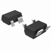
MBC13916NT1 Freescale Semiconductor, MBC13916NT1 Datasheet - Page 9

MBC13916NT1
Manufacturer Part Number
MBC13916NT1
Description
TRANS RF NPN LO NOISE SOT-343
Manufacturer
Freescale Semiconductor
Type
General Purpose Amplifierr
Specifications of MBC13916NT1
Current - Supply
20mA
Frequency
100MHz ~ 2.5GHz
Gain
16.5dB
Noise Figure
1.9dB
P1db
2.5dBm
Package / Case
SOT-343R
Rf Type
General Purpose
Test Frequency
1.9GHz
Voltage - Supply
2.7V ~ 5V
Number Of Channels
1
Operating Frequency
2500 MHz
Operating Supply Voltage
3 V
Supply Current
5.6 mA @ 2.7 V
Maximum Power Dissipation
100 mW
Maximum Operating Temperature
+ 85 C
Minimum Operating Temperature
- 40 C
Mounting Style
SMD/SMT
Technology
Low Noise Amplifier
Manufacturer's Type
Low Noise Amplifier
Frequency (max)
2.5GHz
Operating Supply Voltage (min)
2.7V
Operating Supply Voltage (typ)
3V
Operating Supply Voltage (max)
5V
Package Type
SOT-343R
Mounting
Surface Mount
Pin Count
3 +Tab
Noise Figure (typ)
2.1@1900MHzdB
Operating Temp Range
-40C to 85C
Operating Temperature Classification
Industrial
Lead Free Status / RoHS Status
Lead free / RoHS Compliant
Other names
MBC13916NT1
MBC13916NT1TR
MBC13916NT1TR
Available stocks
Company
Part Number
Manufacturer
Quantity
Price
5
A flexible applications board topology has been developed to demonstrate the performance of the
MBC13900 at 900 and 1900 MHz. The designs are a compromise of the competing performance
requirements of gain, noise figure, input third-order intercept point (IIP3) and return losses. PCB, samples
and assembly information is available from Freescale under part number KITMBC13900.
5.1
Figure 18
design goals for the circuit are:
Freescale Semiconductor
NF < 1.2 dB
Gain > 19 dB
Return Loss > 10 dB, input and output
Unconditional stability from 100 MHz to 6 GHz.
Applications Information
900 MHz LNA
shows the schematic and
Figure 16. One dB Compression Point versus Collector Current
Figure 17. One dB Compression Point versus Collector Current
-2.0
-6.0
-2.0
-6.0
-10
-14
-10
-14
6.0
2.0
6.0
2.0
14
10
14
10
0
0
Figure 19
2.0
MBC13900 Technical Data, Rev. 1.1
2.0
4.0
4.0
I
I
C
C
6.0
6.0
shows the component placement for a 900 MHz LNA. The
, COLLECTOR CURRENT (mA)
, COLLECTOR CURRENT (mA)
8.0
8.0
10
10
12
12
14
14
f = 900 MHz
f = 1.9 GHz
16
16
3.0 V
3.0 V
2.0 V
2.0 V
18
18
20
20
Applications Information
9


