AD8312ACBZ-P7 Analog Devices Inc, AD8312ACBZ-P7 Datasheet - Page 12
AD8312ACBZ-P7
Manufacturer Part Number
AD8312ACBZ-P7
Description
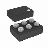
IC DETECTOR RF LOGIC 6-WLCSP
Manufacturer
Analog Devices Inc
Type
Logarithmic Amplifierr
Datasheet
1.AD8312ACBZ-P7.pdf
(20 pages)
Specifications of AD8312ACBZ-P7
Rf Type
Cellular, GSM, CDMA, W-CDMA
Frequency
50MHz ~ 3.5GHz
Input Range
-45dBm ~ 0dBm
Accuracy
±1dB
Voltage - Supply
2.7 V ~ 5.5 V
Current - Supply
5.7mA
Package / Case
6-UFBGA, 6-uCSP
Frequency Range
50MHz To 3.5GHz
Power Range
-45dBm To 0dBm
Sensitivity
0.0073dB/°C
Supply Current
4.2mA
Supply Voltage Range
2.7V To 5.5V
Rf Ic Case Style
WLCSP
Number Of Channels
1
Number Of Elements
1
Power Supply Requirement
Single
Input Resistance
0.013MOhm
Input Bias Current
75uA
Single Supply Voltage (typ)
3V
Dual Supply Voltage (typ)
Not RequiredV
Power Dissipation
200mW
Rail/rail I/o Type
No
Single Supply Voltage (min)
2.7V
Single Supply Voltage (max)
5.5V
Dual Supply Voltage (min)
Not RequiredV
Dual Supply Voltage (max)
Not RequiredV
Operating Temp Range
-40C to 85C
Operating Temperature Classification
Industrial
Mounting
Surface Mount
Pin Count
6
Package Type
WLCSP
Lead Free Status / RoHS Status
Lead free / RoHS Compliant
Lead Free Status / RoHS Status
Lead free / RoHS Compliant, Lead free / RoHS Compliant
Other names
AD8312ACBZ-P7
AD8312ACBZ-P7TR
AD8312ACBZ-P7TR
Available stocks
Company
Part Number
Manufacturer
Quantity
Price
Company:

Part Number:
AD8312ACBZ-P7
Manufacturer:
ADI
Quantity:
9 000
Company:
Part Number:
AD8312ACBZ-P7
Manufacturer:
ST
Quantity:
320


AD8312
GENERAL DESCRIPTION
The AD8312 is a logarithmic amplifier (log amp) similar in
design to the AD8313; further details about the structure and
function may be found in the AD8313 data sheet and the data
sheets of other log amplifiers produced by ADI. Figure 21 shows
the main features of the AD8312 in block schematic form.
The AD8312 combines two key functions needed for the
measurement of signal level over a moderately wide dynamic
range. First, it provides the amplification needed to respond to
small signals in a chain of four amplifier/limiter cells, each
having a small-signal gain of 10 dB and a bandwidth of
approximately 3.5 GHz. At the output of each amplifier stage is
a full-wave rectifier, essentially a square-law detector cell, which
converts the RF signal voltages to a fluctuating current with an
average value that increases with signal level. A further passive
detector stage is added ahead of the first stage. Therefore, there
are five detectors, each separated by 10 dB, spanning some
50 dB of dynamic range. The overall accuracy at the extremes
of this total range, viewed as the deviation from an ideal loga-
rithmic response, that is, the law-conformance error, can be
judged by reference to Figure 3 through Figure 8, which show
that errors across the central 40 dB are moderate. These figures
show how the conformance to an ideal logarithmic function
varies with temperature and frequency.
The output of these detector cells is in the form of a differential
current, making their summation a simple matter. It can easily
be shown that such summation closely approximates a
logarithmic function. This result is then converted to a voltage
at the VOUT pin through a high gain stage. In measurement
modes, this output is connected back to a voltage-to-current
(V-to-I) stage, in such a manner that VOUT is a logarithmic
COMM
RFIN
DET
COMPENSATION
10dB
OFFSET
DET
10dB
Figure 21. Block Schematic
DET
Rev. A | Page 12 of 20
10dB
DET
measure of the RF input voltage with a slope and intercept
controlled by the design. For a fixed termination resistance at
the input of the AD8312, a given voltage corresponds to a
certain power level.
The external termination added before the AD8312 determines
the effective power scaling. This often takes the form of a
simple resistor (52.3 Ω provides a net 50 Ω input), but more
elaborate matching networks may be used. This impedance
determines the logarithmic intercept, the input power for which
the output would cross the baseline (VOUT = 0) if the function
were continuous for all values of input. Since this is never the
case for a practical log amp, the intercept refers to the value
obtained by the minimum-error, straight-line fit to the actual
graph of VOUT vs. input power. The quoted values assume a
sinusoidal (CW) signal. Where there is complex modulation, as
in CDMA, the calibration of the power response needs to be
adjusted accordingly. Where a true power (waveform-
independent) response is needed, the use of an rms-responding
detector, such as the AD8361, should be considered.
However, in terms of the logarithmic slope, the amount by
which the output VOUT changes for each decibel of input
change (voltage or power), is, in principle, independent of
waveform or termination impedance. In practice, it usually falls
off at higher frequencies because of the declining gain of the
amplifier stages and other effects in the detector cells. For the
AD8312, the slope at low frequencies is nominally 21.0 mV/dB,
falling almost linearly with frequency to about 18.6 mV/dB at
2.5 GHz. These values are sensibly independent of temperature
and almost totally unaffected by supply voltages of 2.7 V to 5.5 V.
AD8312
10dB
CFLT
DET
+
REFERENCE
BAND-GAP
–
V-I
I-V
VSET
VOUT
VPOS
Related parts for AD8312ACBZ-P7
Image
Part Number
Description
Manufacturer
Datasheet
Request
R

Part Number:
Description:
High-Performance, Low Distortion 500-MHz Mixer
Manufacturer:
Analog Devices
Datasheet:

Part Number:
Description:
MIXER IC
Manufacturer:
Analog Devices Inc
Datasheet:
Part Number:
Description:
MIXER IC
Manufacturer:
Analog Devices Inc
Datasheet:

Part Number:
Description:
±1.7g Dual-Axis IMEMS Accelerometer Evaluation Board
Manufacturer:
Analog Devices Inc
Datasheet:

Part Number:
Description:
Inertial Sensor Evaluation System
Manufacturer:
Analog Devices Inc
Datasheet:
Part Number:
Description:
Manufacturer:
Analog Devices Inc
Datasheet:
Part Number:
Description:
Manufacturer:
Analog Devices Inc
Datasheet:
Part Number:
Description:
Manufacturer:
Analog Devices Inc
Datasheet:
Part Number:
Description:
Manufacturer:
Analog Devices Inc
Datasheet:
Part Number:
Description:
Manufacturer:
Analog Devices Inc
Datasheet:
Part Number:
Description:
Manufacturer:
Analog Devices Inc
Datasheet:
Part Number:
Description:
Manufacturer:
Analog Devices Inc
Datasheet: