AD8312ACBZ-P7 Analog Devices Inc, AD8312ACBZ-P7 Datasheet - Page 16
AD8312ACBZ-P7
Manufacturer Part Number
AD8312ACBZ-P7
Description
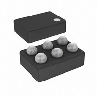
IC DETECTOR RF LOGIC 6-WLCSP
Manufacturer
Analog Devices Inc
Type
Logarithmic Amplifierr
Datasheet
1.AD8312ACBZ-P7.pdf
(20 pages)
Specifications of AD8312ACBZ-P7
Rf Type
Cellular, GSM, CDMA, W-CDMA
Frequency
50MHz ~ 3.5GHz
Input Range
-45dBm ~ 0dBm
Accuracy
±1dB
Voltage - Supply
2.7 V ~ 5.5 V
Current - Supply
5.7mA
Package / Case
6-UFBGA, 6-uCSP
Frequency Range
50MHz To 3.5GHz
Power Range
-45dBm To 0dBm
Sensitivity
0.0073dB/°C
Supply Current
4.2mA
Supply Voltage Range
2.7V To 5.5V
Rf Ic Case Style
WLCSP
Number Of Channels
1
Number Of Elements
1
Power Supply Requirement
Single
Input Resistance
0.013MOhm
Input Bias Current
75uA
Single Supply Voltage (typ)
3V
Dual Supply Voltage (typ)
Not RequiredV
Power Dissipation
200mW
Rail/rail I/o Type
No
Single Supply Voltage (min)
2.7V
Single Supply Voltage (max)
5.5V
Dual Supply Voltage (min)
Not RequiredV
Dual Supply Voltage (max)
Not RequiredV
Operating Temp Range
-40C to 85C
Operating Temperature Classification
Industrial
Mounting
Surface Mount
Pin Count
6
Package Type
WLCSP
Lead Free Status / RoHS Status
Lead free / RoHS Compliant
Lead Free Status / RoHS Status
Lead free / RoHS Compliant, Lead free / RoHS Compliant
Other names
AD8312ACBZ-P7
AD8312ACBZ-P7TR
AD8312ACBZ-P7TR
Available stocks
Company
Part Number
Manufacturer
Quantity
Price
Company:

Part Number:
AD8312ACBZ-P7
Manufacturer:
ADI
Quantity:
9 000
Company:
Part Number:
AD8312ACBZ-P7
Manufacturer:
ST
Quantity:
320


AD8312
Temperature Drift
Figure 30 shows the log slope and error over temperature for a
0.9 GHz input signal. Error due to drift over temperature
consistently remains within ±0.5 dB and only begins to exceed
this limit when the ambient temperature goes above 70°C. For
all frequencies using a reduced temperature range, higher
measurement accuracy is achievable.
Operation Above 2.5 GHz
The AD8312 works at high frequencies, but exhibits slightly
higher output voltage temperature drift. Figure 31 and Figure 32
show the transfer functions and error distributions of a large
population of devices at 3.0 GHz and 3.5 GHz over
temperature. Due to the repeatability of the drift from part-to-
part, compensation can be applied to reduce the effects of
temperature drift. In the case of the 3.5 GHz distribution, an
intercept correction of 2.0 dB at 85°C would improve the
accuracy of the distribution to ±2 dB over a +40 dB range.
1.3
1.0
0.8
0.5
0.3
0
–60
Figure 30. Typical Drift at 900 GHz for Various Temperatures
–1
–2
–3
–4
–5
5
4
3
2
1
0
–60
–50
Figure 29. Shift in Transfer Function due to
–50
Several Different Signal Waveforms
–40
WCDMA 64-CH
CW
–40
–30
P
INPUT (dBm)
–30
IN
(dBm)
–20
IS-95 REV
–20
64 QAM
+85°C
+70°C
+25°C
0°C
–10°C
–20°C
–40°C
–10
–10
0
0
10
10
2.5
2.0
1.5
1.0
0.5
0
–0.5
–1.0
–1.5
–2.0
–2.5
Rev. A | Page 16 of 20
Device Handling
The wafer-level chip scale package consists of solder bumps
connected to the active side of the die. The part is lead-free with
95.5% tin, 4.0% silver, and 0.5% copper solder bump comp-
osition. The WLCSP package can be mounted on printed circuit
boards using standard surface-mount assembly techniques;
however, caution should be taken to avoid damaging the die.
See the AN-617 application note for additional information.
WLCSP devices are bumped die, and exposed die can be
sensitive to light condition, which can influence specified limits.
Evaluation Board
Figure 33 shows the schematic of the AD8312 evaluation board.
The layout and silkscreen of the component and circuit sides
are shown in Figure 34 to Figure 37. The board is powered by a
single supply in the 2.7 V to 5.5 V range. The power supply is
decoupled by a single 0.1 μF capacitor.
Table 6 details the various configuration options of the
evaluation board.
Ambient Normalization vs. Input Amplitude at 3.0 GHz for 60 Devices
Figure 32. Output Voltage and Error at −40°C, +25°C, and +85°C After
Ambient Normalization vs. Input Amplitude at 3.5 GHz for 30 Devices
Figure 31.Output Voltage and Error at −40°C, +25°C, and +85°C After
1.0
0.9
0.8
0.7
0.6
0.5
0.4
0.3
0.2
0.1
1.0
0.9
0.8
0.7
0.6
0.5
0.4
0.3
0.2
0.1
0
0
–55
–55
–45
–45
–35
–35
+85°C
+25°C
+85°C
+25°C
–40°C
–40°C
P
P
IN
IN
–25
–25
(dBm)
(dBm)
–15
–15
–5
–5
5
5
5
4
3
2
1
0
–1
–2
–3
–4
–5
5
4
3
2
1
0
–1
–2
–3
–4
–5
Related parts for AD8312ACBZ-P7
Image
Part Number
Description
Manufacturer
Datasheet
Request
R

Part Number:
Description:
High-Performance, Low Distortion 500-MHz Mixer
Manufacturer:
Analog Devices
Datasheet:

Part Number:
Description:
MIXER IC
Manufacturer:
Analog Devices Inc
Datasheet:
Part Number:
Description:
MIXER IC
Manufacturer:
Analog Devices Inc
Datasheet:

Part Number:
Description:
±1.7g Dual-Axis IMEMS Accelerometer Evaluation Board
Manufacturer:
Analog Devices Inc
Datasheet:

Part Number:
Description:
Inertial Sensor Evaluation System
Manufacturer:
Analog Devices Inc
Datasheet:
Part Number:
Description:
Manufacturer:
Analog Devices Inc
Datasheet:
Part Number:
Description:
Manufacturer:
Analog Devices Inc
Datasheet:
Part Number:
Description:
Manufacturer:
Analog Devices Inc
Datasheet:
Part Number:
Description:
Manufacturer:
Analog Devices Inc
Datasheet:
Part Number:
Description:
Manufacturer:
Analog Devices Inc
Datasheet:
Part Number:
Description:
Manufacturer:
Analog Devices Inc
Datasheet:
Part Number:
Description:
Manufacturer:
Analog Devices Inc
Datasheet: