DEMOBOARD-T7024PGM Atmel, DEMOBOARD-T7024PGM Datasheet - Page 10
DEMOBOARD-T7024PGM
Manufacturer Part Number
DEMOBOARD-T7024PGM
Description
BOARD DEMO FOR T7024PGM
Manufacturer
Atmel
Type
Bluetoothr
Specifications of DEMOBOARD-T7024PGM
Frequency
2.4GHz
Processor Series
T7024
Wireless Frequency
2.4 GHz
For Use With/related Products
T7024PGM
Lead Free Status / RoHS Status
Contains lead / RoHS non-compliant
Other names
DEMOBOARD-T7024-PGM


Switch Driver
Application Board
Connectors
10
Design Guide T7024
The switch driver of the T7024 front end is used to realize an antenna switch. A
switched current source is used for this purpose. The supply of the LNA is also used for
the switch driver. The switch driver is turned on with the control signals PU on high and
RX_ON on low.
A typical application of the switch driver is shown in Figure 11.
Figure 11. Antenna Switch with the T7024
The operation of the antenna switch is as follows.
If the LNA and switch driver are in receive mode (RX_ON = high), the switch-out port
draws no current. In this case, the diodes can be seen as a high impedance and the
LNA input is connected directly to the antenna.
In transmit mode, the RX_ON signal is toggled to low. The switch-out port draws current
to ground and the diodes are switched to a low impedance. The PA output is connected
directly to the antenna, the quarter wavelength transmission line between the two
diodes transforms the short of the capacitor at the switch-out connector to an open at
the diode in the PA output line. Therefore, the LNA input is separated from the PA out-
put and the high output power cannot be delivered to the LNA input. The switch-out
current is adjusted between approximately 1.7 mA and 19 mA using a reference resistor
at the R_SWITCH pin.
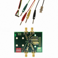
However, the antenna switch is not realized on the application board, thus enabling
good access to the LNA input and the PA output. Instead of PIN diodes, the application
board is equipped with two LEDs for visualization purposes.
The application uses four SMA female connectors for the RF signals: LNA in, LNA out,
PA in, and PA out. The DC connections are realized by two connectors, one for the PA
with lines for ramp, ground and the supply voltages for the three-amplifier stages:
V1_PA, V2_PA, and V3_PA, and one connector for the LNA with lines for the supply
voltage, ground, switch current, PU (power up) and RX_ON.
The two connectors are shown in Figure 12 on page 11.
SWITCH out
T7024
LNA in
match
LNA
l/4
PA out
match
PA
antenna
DC supply
4549D–BLURF–06/04
Related parts for DEMOBOARD-T7024PGM
Image
Part Number
Description
Manufacturer
Datasheet
Request
R

Part Number:
Description:
BOARD DEMO FOR U4091BM
Manufacturer:
Atmel
Datasheet:


Part Number:
Description:
BOARD DEMO FOR U3600BM
Manufacturer:
Atmel
Datasheet:

Part Number:
Description:
BOARD DEMO FOR ATR2806
Manufacturer:
Atmel
Datasheet:
Part Number:
Description:
BOARD DEMO COM-I/Q MOD 1GHZ
Manufacturer:
Atmel
Datasheet:

Part Number:
Description:
Banana & Binding Post Connectors SINGLE PCB SOCK BLK
Manufacturer:
DEM Manufacturing
Datasheet:
Part Number:
Description:
Banana & Binding Post Connectors PLUG RED
Manufacturer:
DEM Manufacturing
Datasheet:
Part Number:
Description:
Banana & Binding Post Connectors SINGLE PCB SOCK RED
Manufacturer:
DEM Manufacturing
Datasheet:
Part Number:
Description:
DIN Connectors SOCKET NICKEL 8 PIN
Manufacturer:
DEM Manufacturing
Datasheet:
Part Number:
Description:
DIN Connectors PLUG NICKEL 3 PIN
Manufacturer:
DEM Manufacturing
Datasheet: