DEMOBOARD-T7024PGM Atmel, DEMOBOARD-T7024PGM Datasheet - Page 9
DEMOBOARD-T7024PGM
Manufacturer Part Number
DEMOBOARD-T7024PGM
Description
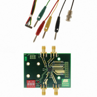
BOARD DEMO FOR T7024PGM
Manufacturer
Atmel
Type
Bluetoothr
Specifications of DEMOBOARD-T7024PGM
Frequency
2.4GHz
Processor Series
T7024
Wireless Frequency
2.4 GHz
For Use With/related Products
T7024PGM
Lead Free Status / RoHS Status
Contains lead / RoHS non-compliant
Other names
DEMOBOARD-T7024-PGM


Low-noise Amplifier
4549D–BLURF–06/04
The Low-Noise Amplifier (LNA) of the T7024 is a two-stage amplifier with an internal
matching at 2.45 GHz. The LNA includes DC supply, RF input, RF output, two control
signals and ground connections. To achieve good noise figure values, it is recom-
mended that blocking capacitors at the DC supply of the LNA are used.
The RF input is DC-coupled to the internal circuitry. A DC blocking capacitor is therefore
necessary at the RF input. This blocking capacitor should also be used for the matching
of the input port. A 1.8 pF capacitor is used on the reference designs for matching to
50
The RF output of the LNA has an internal DC blocking capacitor, therefore, external DC
blocking is not necessary. Since the LNA output has only a minor influence on the noise
figure, it is sufficient to design an output network with a good match to 50 .
The LNA and the switch driver are controlled by the PU and the RX_ON control pin. A
PU high signal switches the LNA from standby mode with low quiescent current to active
mode. The RX_ON signal toggles between LNA (RX_ON high) and switch driver
(RX_ON low), since the switch driver and the LNA are not used simultaneously, see fur-
ther design considerations in the next paragraph.
The gain of the integrated LNA may be controlled by an analogue signal at the RX_ON
pin. This feature can be used - together with an automatic gain control (AGC) loop in a
transceiver - to get optimum signal power level at the receive input of the transceiver.
Figure 10 shows the correspondence between RX_ON control voltage and LNA gain.
Please note, that below approximately 1.4 V at RX_ON the LNA/antenna control cir-
cuitry switches to transmit mode. Usually, this behavior should be omitted, since a sharp
step with additional gain loss of about 15 to 20 dB (depending on antenna switch perfor-
mance) occurs.
However, if a transceiver can handle this sharp gain step, it may be possible to use this
switching as an additional benefit under high power reception.
Figure 10. Gain of T7024 LNA versus RX_ON Voltage
and noise matching.
-25
-15
25
15
-5
5
1.0
1.5
RX_ON (V)
2.0
Design Guide T7024
Gain (dB)
2.5
3.0
9
Related parts for DEMOBOARD-T7024PGM
Image
Part Number
Description
Manufacturer
Datasheet
Request
R

Part Number:
Description:
BOARD DEMO FOR U4091BM
Manufacturer:
Atmel
Datasheet:


Part Number:
Description:
BOARD DEMO FOR U3600BM
Manufacturer:
Atmel
Datasheet:

Part Number:
Description:
BOARD DEMO FOR ATR2806
Manufacturer:
Atmel
Datasheet:
Part Number:
Description:
BOARD DEMO COM-I/Q MOD 1GHZ
Manufacturer:
Atmel
Datasheet:

Part Number:
Description:
Banana & Binding Post Connectors SINGLE PCB SOCK BLK
Manufacturer:
DEM Manufacturing
Datasheet:
Part Number:
Description:
Banana & Binding Post Connectors PLUG RED
Manufacturer:
DEM Manufacturing
Datasheet:
Part Number:
Description:
Banana & Binding Post Connectors SINGLE PCB SOCK RED
Manufacturer:
DEM Manufacturing
Datasheet:
Part Number:
Description:
DIN Connectors SOCKET NICKEL 8 PIN
Manufacturer:
DEM Manufacturing
Datasheet:
Part Number:
Description:
DIN Connectors PLUG NICKEL 3 PIN
Manufacturer:
DEM Manufacturing
Datasheet: