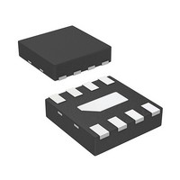
AMMP-6530-TR1 Avago Technologies US Inc., AMMP-6530-TR1 Datasheet - Page 7

AMMP-6530-TR1
Manufacturer Part Number
AMMP-6530-TR1
Description
IC MMIC REJECT MXR 5-30GHZ 8-SMD
Manufacturer
Avago Technologies US Inc.
Series
AMMP-6530r
Datasheet
1.AMMP-6530-TR2.pdf
(11 pages)
Specifications of AMMP-6530-TR1
Frequency
5GHz ~ 30GHz
Function
Mixer
Rf Type
ISM; DBS; VSAT; 802.16/WiMax; WLL; MMDS
Package / Case
8-QFN
Rf Ic Case Style
SMD
No. Of Pins
8
Operating Temperature Range
-55°C To +125°C
Frequency Max
30GHz
Ic Function
Image Reject Mixer
Termination Type
SMD
Supply Voltage Max
0V
Filter Terminals
SMD
Rohs Compliant
Yes
Digital Ic Case Style
SMD
Gain Typ, V/v
-10
Lead Free Status / RoHS Status
Lead free / RoHS Compliant
Lead Free Status / RoHS Status
Lead free / RoHS Compliant, Lead free / RoHS Compliant
Available stocks
Company
Part Number
Manufacturer
Quantity
Price
Part Number:
AMMP-6530-TR1
Manufacturer:
AVAGO/安华高
Quantity:
20 000
Biasing and Operation
The recommended DC bias condition for optimum
performance, and reliability is Vg = -1 volts. There is no
current consumption for the gate biasing because the
FET mixer was designed for passive operation. For down
conversion, the AMMP-6530 may be configured in a low
loss or high linearity application. In a low loss configura-
tion, the LO is applied through the drain (Pin8, power
divider side). In this configuration, the AMMP-6530 is a
“drain pumped mixer” . For higher linearity applications,
the LO is applied through the gate (Pin4, Lange coupler
side). In this configuration, the AMMP-6530 is a “gate
pumped mixer” (or Resistive mixer). The mixer is also
suitable for up-conversion applications under the gate
pumped mixer operation shown on page 3.
Please note that the image rejection and isolation
performance is dependent on the selection of the
low frequency quadrature hybrid. The performance
specification of the low frequency quadrature hybrid
as well as the phase balance and VSWR of the interface
to the AMMP-6530 will affect the overall mixer perfor-
mance.
7
Figure 21. Simplified MMIC Schematic.
LO/RF
Figure 22. Demonstration Board (available upon request).
7
6
5
NC
NC
Vg
drain
8
4
gate
IF1
NC
IF2
Gnd Vg
IF1
1
2
3
IF2
RF/LO


