MICRF211AYQS Micrel Inc, MICRF211AYQS Datasheet - Page 14

MICRF211AYQS
Manufacturer Part Number
MICRF211AYQS
Description
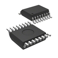
IC RX 3V 380-450 MHZ 16-QSOP
Manufacturer
Micrel Inc
Specifications of MICRF211AYQS
Operating Temperature
-40°C ~ 105°C
Frequency
380MHz ~ 450MHz
Sensitivity
-110dBm
Data Rate - Maximum
10 kbps
Modulation Or Protocol
ASK, OOK
Applications
ISM, Garage Door Openers, RKE
Current - Receiving
6mA
Data Interface
PCB, Surface Mount
Antenna Connector
PCB, Surface Mount
Features
No IF Filter Required
Voltage - Supply
3 V ~ 3.6 V
Package / Case
16-QSOP
Data Rate
1Kbps
Frequency Range
380MHz To 450MHz
Modulation Type
ASK, OOK
Sensitivity Dbm
-110dBm
Rf Ic Case Style
QSOP
No. Of Pins
16
Supply Voltage Range
3V To 3.6V
Operating Frequency (max)
450000kHz
Operating Temperature (min)
-40C
Operating Temperature (max)
105C
Operating Temperature Classification
Industrial
Operating Supply Voltage (typ)
3.3V
Operating Supply Voltage (max)
3.6V
Lead Free Status / RoHS Status
Lead free / RoHS Compliant
Memory Size
-
Lead Free Status / Rohs Status
Compliant
Other names
576-1964-5
MICRF211AYQS
MICRF211AYQS
Available stocks
Company
Part Number
Manufacturer
Quantity
Price
Part Number:
MICRF211AYQS-TR
Manufacturer:
MICROCHIP/微芯
Quantity:
20 000
March 2007
Micrel
PCB Considerations and Layout
Figure 12 to 17 below show some of the printed circuit
layers for the QR211HE1 board. Use the Gerber files
provided (downloadable from Micrel Website) which
have the remaining layers needed to fabricate this
board. When copying or making your own boards,
make traces as short as possible. Long traces alter
the matching network and the values suggested are
no longer valid. Suggested Matching Values may vary
due to PCB variations. A PCB trace 100 mills (2.5mm)
long has about 1.1nH inductance. Optimization should
always be done with exhaustive range tests. Make
individual ground connections to the ground plane
with a Via for each ground connection. Do not share
Vias
with
ground
connections.
Figure 13. QR211HE1 Bottom Layer, Mirror Image.
Each
Figure 12. QR211HE1 Top Layer.
ground
14
connection = 1 via or more vias. Ground plane must
be solid and possibly without interruptions. Avoid
ground plane on top next to the matching elements. It
normally adds additional stray capacitance which
changes the matching. Do not use phenolic material,
only FR4 or better materials. Phenolic material is
conductive above 200MHz. RF path should be as
straight as possible avoiding loops and unnecessary
turns. Separate ground and V
circuits (microcontroller, etc). Known sources of noise
should be laid out as far as possible from the RF
circuits. Avoid thick traces, the higher the frequency,
the thinner the trace should be in order to minimize
losses in the RF path.
DD
lines from other
(408) 944-0800
M9999-030107
MICRF211


