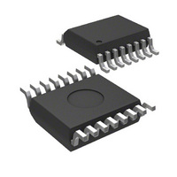
MICRF211AYQS Micrel Inc, MICRF211AYQS Datasheet - Page 9

MICRF211AYQS
Manufacturer Part Number
MICRF211AYQS
Description
IC RX 3V 380-450 MHZ 16-QSOP
Manufacturer
Micrel Inc
Specifications of MICRF211AYQS
Operating Temperature
-40°C ~ 105°C
Frequency
380MHz ~ 450MHz
Sensitivity
-110dBm
Data Rate - Maximum
10 kbps
Modulation Or Protocol
ASK, OOK
Applications
ISM, Garage Door Openers, RKE
Current - Receiving
6mA
Data Interface
PCB, Surface Mount
Antenna Connector
PCB, Surface Mount
Features
No IF Filter Required
Voltage - Supply
3 V ~ 3.6 V
Package / Case
16-QSOP
Data Rate
1Kbps
Frequency Range
380MHz To 450MHz
Modulation Type
ASK, OOK
Sensitivity Dbm
-110dBm
Rf Ic Case Style
QSOP
No. Of Pins
16
Supply Voltage Range
3V To 3.6V
Operating Frequency (max)
450000kHz
Operating Temperature (min)
-40C
Operating Temperature (max)
105C
Operating Temperature Classification
Industrial
Operating Supply Voltage (typ)
3.3V
Operating Supply Voltage (max)
3.6V
Lead Free Status / RoHS Status
Lead free / RoHS Compliant
Memory Size
-
Lead Free Status / Rohs Status
Compliant
Other names
576-1964-5
MICRF211AYQS
MICRF211AYQS
Available stocks
Company
Part Number
Manufacturer
Quantity
Price
Part Number:
MICRF211AYQS-TR
Manufacturer:
MICROCHIP/微芯
Quantity:
20 000
March 2007
Micrel
For the frequency of 433.92MHz, the input impedance
is Z = 18.6 – j174.2Ω, then the matching components
are calculated by,
Equivalent parallel = B = 1/Z = 0.606 + j5.68 msiemens
Rp = 1 / Re (B);
Rp = 1.65kΩ;
Q = SQRT (Rp/50 + 1)
Q = 5.831
Xm = Rp / Q
Xm = 282.98Ω
Resonance Method For L-shape Matching Network
Lc = Xp / (2×Pi×f);
L2 = (Lc×Lp) / (Lc + Lp);
L2 = 39.8nH
C3 = 1.3pF
Doing the same calculation example with the Smith
Chart, it would appear as follows,
First, we plot the input impedance of the device,
(Z = 18.6 – j174.2)Ω @ 433.92MHz.(Figure 4).
Table 4: matching values for the most used frequencies
Freq (MHz)
390.0
418.0
433.92
Xp = 176.2Ω
C3 (pF)
1.5
1.5
1.5
L2(nH)
47
43
39
Xp = 1 / Im (B)
Lp = Xm / (2×Pi×f)
C3 = 1 / (2×Pi×f×Xm)
22.5 – j198.5
21.4 – j186.1
18.6 – j174.2
Z device (Ω)
9
Second, we plot the shunt inductor (39nH) and the
series capacitor (1.5pF) for the desired input
impedance (Figure 5). We can see the matching
leading to the center of the Smith Chart or close to
50Ω.
Figure 4: device’s input impedance, Z = 18.6 – j174.2Ω
Figure 5. Plotting the Shunt Inductor and Series
Capacitor.
(408) 944-0800
M9999-030107
MICRF211


