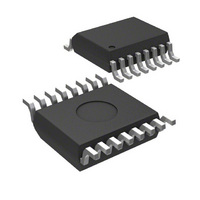
MICRF211AYQS Micrel Inc, MICRF211AYQS Datasheet - Page 8

MICRF211AYQS
Manufacturer Part Number
MICRF211AYQS
Description
IC RX 3V 380-450 MHZ 16-QSOP
Manufacturer
Micrel Inc
Specifications of MICRF211AYQS
Operating Temperature
-40°C ~ 105°C
Frequency
380MHz ~ 450MHz
Sensitivity
-110dBm
Data Rate - Maximum
10 kbps
Modulation Or Protocol
ASK, OOK
Applications
ISM, Garage Door Openers, RKE
Current - Receiving
6mA
Data Interface
PCB, Surface Mount
Antenna Connector
PCB, Surface Mount
Features
No IF Filter Required
Voltage - Supply
3 V ~ 3.6 V
Package / Case
16-QSOP
Data Rate
1Kbps
Frequency Range
380MHz To 450MHz
Modulation Type
ASK, OOK
Sensitivity Dbm
-110dBm
Rf Ic Case Style
QSOP
No. Of Pins
16
Supply Voltage Range
3V To 3.6V
Operating Frequency (max)
450000kHz
Operating Temperature (min)
-40C
Operating Temperature (max)
105C
Operating Temperature Classification
Industrial
Operating Supply Voltage (typ)
3.3V
Operating Supply Voltage (max)
3.6V
Lead Free Status / RoHS Status
Lead free / RoHS Compliant
Memory Size
-
Lead Free Status / Rohs Status
Compliant
Other names
576-1964-5
MICRF211AYQS
MICRF211AYQS
Available stocks
Company
Part Number
Manufacturer
Quantity
Price
Part Number:
MICRF211AYQS-TR
Manufacturer:
MICROCHIP/微芯
Quantity:
20 000
March 2007
Micrel
Application Information
The MICRF211 can be fully tested by using one of
many evaluation boards designed at Micrel for this
device. As an entry level, the QR211HE1 (Figure 3)
offers a good start for most applications. It has a
helical PCB antenna with its matching network, a
band-pass-filter front-end as a pre-selector filter,
matching network and the minimum components
required to make the device work, which are a crystal,
Cagc, and Cth capacitors. By removing the matching
network of the helical PCB antenna (C9 and L3), a
whip antenna (ANT2) or a RF connector (J2) can be
used instead. Figure 3 shows the entire schematic of
it for 433.92MHz. Other frequencies can be used and
the values needed are in the tables below.
Capacitor C9 and inductor L3 are the passive
elements for the helical PCB matching network. A
tight tolerance is recommended for these devices, like
2% for the inductor and 0.1pF for the capacitor. PCB
variations
optimization. Table 2 shows the matching elements
for the device frequency range. For additional
information look for Small PCB Antennas for Micrel RF
Products application note.
To use another antenna, like the whip kind, remove
C9 and place the whip antenna in the hole provided in
the PCB. Also, a RF signal can be injected there.
L1 and C8 form the pass-band-filter front-end. Its
purpose is to attenuate undesired outside band noise
Freq (MHz)
390.0
418.0
433.92
Table 2. Matching Values for the Helical PCB Antenna
may
require
C9 (pF)
1.2
1.2
1.5
different
Figure 3 – QR211HE1 Application Example, 433.92 MHz
L3(nH)
values
43
36
30
and
8
which reduces the receiver performance. It is
calculated
f = 1/(2×PI×(SQRT L1×C8)). Table 3 shows the most
used frequency values.
There is no need for the band-pass-filter front-end for
applications where it is proven that the outside band
noise does not cause a problem. The MICRF211 has
image reject mixers which improve significantly the
selectivity and rejection of outside band noise.
Capacitor C3 and inductor L2 form the L-shape
matching network. The capacitor provides additional
attenuation for low frequency outside band noise and
the inductor provides additional ESD protection for the
antenna pin. Two methods can be used to find these
values, which are matched close to 50Ω. One method
is done by calculating the values using the equations
below and another by using a Smith chart. The latter
is made easier by using software that plots the values
of the components C8 and L1, like WinSmith by Noble
Publishing.
To calculate the matching values, one needs to know
the input impedance of the device. Table 4 shows the
input impedance of the MICRF211 and suggested
matching values for the most used frequencies. These
suggested values may be different if the layout is not
exactly the same as the one made here.
390.0
418.0
433.92
Freq (MHz)
Table 3. Band-Pass-Filter Front-End Values
by
the
parallel
C8 (pF)
6.8
6.0
5.6
resonance
(408) 944-0800
M9999-030107
L1(nH)
24
24
24
MICRF211
equation


