MRF49XA-I/ST Microchip Technology, MRF49XA-I/ST Datasheet - Page 41
MRF49XA-I/ST
Manufacturer Part Number
MRF49XA-I/ST
Description
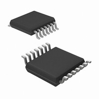
IC RF TXRX 433/868/915 16-TSSOP
Manufacturer
Microchip Technology
Datasheet
1.MRF49XA-IST.pdf
(102 pages)
Specifications of MRF49XA-I/ST
Package / Case
16-TSSOP
Frequency
433MHz, 868MHz, 915MHz
Data Rate - Maximum
256kbps
Modulation Or Protocol
FHSS, FSK
Applications
Home / Industrial Automation, Remote Access, Security Alarms
Power - Output
7dbm
Sensitivity
-110dBm
Voltage - Supply
2.2 V ~ 3.8 V
Current - Receiving
11mA
Current - Transmitting
15mA
Data Interface
PCB, Surface Mount
Antenna Connector
PCB, Surface Mount
Operating Temperature
-40°C ~ 85°C
Number Of Receivers
1
Number Of Transmitters
2
Wireless Frequency
433 MHz to 915 MHz
Output Power
+ 7 dBm
Operating Supply Voltage
2.5 V, 3.3 V
Maximum Operating Temperature
+ 85 C
Mounting Style
SMD/SMT
Minimum Operating Temperature
- 40 C
Modulation
FHSS, FSK
Lead Free Status / RoHS Status
Lead free / RoHS Compliant
Memory Size
-
Lead Free Status / Rohs Status
Lead free / RoHS Compliant
Other names
579-MRF49XA-1/ST
Available stocks
Company
Part Number
Manufacturer
Quantity
Price
Company:

Part Number:
MRF49XA-I/ST
Manufacturer:
IR
Quantity:
450
Part Number:
MRF49XA-I/ST
Manufacturer:
MICROCHIP/微芯
Quantity:
20 000


REGISTER 2-15:
EQUATION 2-8:
© 2009 Microchip Technology Inc.
bit 15
bit 7
Legend:
R = Readable bit
-n = Value at POR
bit 15-8
bit 7-1
bit 0
Note 1:
DC = (DCMV<7:1> x 2 + 1)/WTMV<7:0> x 100%
where:
WTMV is WTMV<7:0> bits of the WTSREG.
R/W-1
R/W-0
For operation in Duty Cycle mode, the receiver must be disabled (RXCEN = 0) and the wake-up timer
must be enabled (WUTEN = 1) in PMCREG. The registers, DCSREG and WTSREG, can be used to
reduce the current consumption of the receiver. The DCSREG can be set up so that when the wake-up
timer brings the MRF49XA out of Sleep mode, the receiver is turned on for a short period to sample the
signal presence before returning to Sleep. The process in the Duty Cycle mode starts over. The duty cycle
uses the multiplier value of the wake-up timer, in parts for its calculation, as shown in Equation 2-8.
CCB<15:8>: Command Code bits
The command code bits (11001000b) are serially sent to the microcontroller to identify the bits to be
written in the DCSREG.
DCMV<6:0>: Duty Cycle Multiplier Value bits
These bits are used to calculate the duty cycle or on time of the receiver after the wake-up timer has
brought the MRF49XA out of Sleep mode.
DCMEN: Duty Cycle Mode Enable bit
1 = Enables the Duty Cycle mode
0 = Disables the Duty Cycle mode
R/W-1
R/W-0
DCSREG: DUTY CYCLE VALUE SET REGISTER (POR: 0xC80E)
r = reserved bit
W = Writable bit
‘1’ = Bit is set
R/W-0
R/W-0
DCMV<6:0>
R/W-0
R/W-0
Preliminary
CCB<15:8>
(1)
U = Unimplemented bit, read as ‘0’
‘0’ = Bit is cleared
R/W-1
R/W-1
R/W-0
R/W-1
x = Bit is unknown
MRF49XA
R/W-0
R/W-1
DS70590B-page 39
DCMEN
R/W-0
R/W-0
bit 8
bit 0
Related parts for MRF49XA-I/ST
Image
Part Number
Description
Manufacturer
Datasheet
Request
R

Part Number:
Description:
Manufacturer:
Microchip Technology Inc.
Datasheet:
Part Number:
Description:
Manufacturer:
Microchip Technology Inc.
Datasheet:
Part Number:
Description:
Manufacturer:
Microchip Technology Inc.
Datasheet:
Part Number:
Description:
Manufacturer:
Microchip Technology Inc.
Datasheet:
Part Number:
Description:
Manufacturer:
Microchip Technology Inc.
Datasheet:
Part Number:
Description:
Manufacturer:
Microchip Technology Inc.
Datasheet:
Part Number:
Description:
Manufacturer:
Microchip Technology Inc.
Datasheet:
Part Number:
Description:
Manufacturer:
Microchip Technology Inc.
Datasheet:
Part Number:
Description:
Manufacturer:
Microchip Technology Inc.
Datasheet: