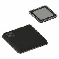
XE1205I074TRLF Semtech, XE1205I074TRLF Datasheet - Page 17

XE1205I074TRLF
Manufacturer Part Number
XE1205I074TRLF
Description
IC TXRX 433/868/915MHZ 48-VQFN
Manufacturer
Semtech
Datasheet
1.XE1205SKC915XE1.pdf
(48 pages)
Specifications of XE1205I074TRLF
Frequency
180MHz Center
Data Rate - Maximum
152.3kbps
Modulation Or Protocol
FSK
Applications
AMR, ISM, Home Automation, Process Control
Power - Output
0 ~ 15dBm
Sensitivity
-121dBm
Voltage - Supply
2.4 V ~ 3.6 V
Current - Receiving
14mA
Current - Transmitting
62mA
Data Interface
PCB, Surface Mount
Antenna Connector
PCB, Surface Mount
Operating Temperature
-40°C ~ 85°C
Package / Case
48-VQFN
Receiving Current
14mA
Transmitting Current
62mA
Data Rate
4.8Kbps
Modulation Type
FSK
Rf Ic Case Style
VQFN
No. Of Pins
48
Supply Voltage Range
2.4V To 3.6V
Operating Temperature (min)
-40C
Operating Temperature (max)
85C
Operating Temperature Classification
Industrial
Operating Supply Voltage (typ)
2.5/3.3V
Operating Supply Voltage (max)
3.6V
Rohs Compliant
Yes
Lead Free Status / RoHS Status
Lead free / RoHS Compliant
Memory Size
-
Lead Free Status / Rohs Status
Compliant
Other names
XE1205I074TR
5.2.5.2
In buffered mode the bit synchronizer is automatically enabled (DCLK is not externally available).
5.2.5.3
In buffered mode the pattern recognition block is automatically enabled. The PATTERN signal m
IR
5.2.5.4
In buffered mode the Received Signal Strength Indica
m
mode.
5.2.5.5
I
5.2.3.5 for more details.
5.2.6
T
re
reduce
Activating this option is advised for bit rates and frequency deviations not higher than 4.8 kbit/s and 5 kHz and if the LO
frequency of the receiver is well controlled, for instance by means of a very accurate crystal or the activation of an AFC.
T
bandwidths.
Table 9 below gives the
It can be
deviations.
© Semtech 2008
n buffe
he lowest bandwidth for the base
he table below gives the sensitivity and the adjacent channel rejection for BR = 4.8 kbit/s and Δf = 5 kHz for different
ode, however, RSSI_irq may be mapped to IRQ_1 (please refer to section 5.2.2) instead of to IRQ_0 in continuous
gister is 10 kHz. However, as described in section 7.2.8, additional register settings allow this bandwidth to be further
Q_0. Please refer to section 5.2.2 for further details.
Bandwidth
Bandwidth
d.
SSB
SSB
red mode the Frequency Error Indication operates the same way as in continuous mode. Please refer to section
10 kHz
10 kHz
9 kHz
8 kHz
7 kHz
9 kHz
8 kHz
7 kHz
This option allows the user to improve the se
seen from table
Additional narrowband filter bandwidths
Bit synchronizer in buffered mode
Pattern recognition block in buffere
RSSI in buffered mode
Frequency Error Indicator in buffered mode – FEI
TParam_Low _BW
TParam_Low _BW
sensitivity and the adjacent channel rejection for BR = 1.2 kbit/s and f = 2 kHz.
Table 8: Performances of the recei
Table 9: Performances of the r
9 that this option also allows the sensitivity to be improved for very low
0
1
1
1
0
1
1
1
-band filter which can be selected by changing only a 2-bit word in the configuration
TParam_Code_BW(8:0)
TParam_Code_BW(8:0)
d mode
eceiver
139
160
185
X
lectivity of the receiver for very narrow-band applications.
tion operates the same way as in continuous mode. In buffered
ver fo
139
160
185
X
for very narrow
17
r very narro
(BER=0.1%)
Sensitivity
w bandwidths
-115.5 dBm
-117.5 dBm
-119.5 dBm
(BER=0.1%)
Sensitivity
-118 dBm
-119 dBm
-116 dBm
-116 dBm
-115 dBm
RFS
bandwidth
RFS
s and 1.2 kbit/s
and 4.8 kbit/s
Adjacent Channel Rejection
Adjacent Channel Rejection
(25 kHz offset sing
(25 kHz offset single tone)
Δ
ACR
ACR
bit rates
18 dBc
23 dBc
28 dBc
33 dBc
20 dBc
25 dBc
30 dBc
35 dBc
ay be mapped to pin
XE1205
le tone)
www.semtech.com
and frequency


