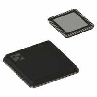
XE1205I074TRLF Semtech, XE1205I074TRLF Datasheet - Page 36

XE1205I074TRLF
Manufacturer Part Number
XE1205I074TRLF
Description
IC TXRX 433/868/915MHZ 48-VQFN
Manufacturer
Semtech
Datasheet
1.XE1205SKC915XE1.pdf
(48 pages)
Specifications of XE1205I074TRLF
Frequency
180MHz Center
Data Rate - Maximum
152.3kbps
Modulation Or Protocol
FSK
Applications
AMR, ISM, Home Automation, Process Control
Power - Output
0 ~ 15dBm
Sensitivity
-121dBm
Voltage - Supply
2.4 V ~ 3.6 V
Current - Receiving
14mA
Current - Transmitting
62mA
Data Interface
PCB, Surface Mount
Antenna Connector
PCB, Surface Mount
Operating Temperature
-40°C ~ 85°C
Package / Case
48-VQFN
Receiving Current
14mA
Transmitting Current
62mA
Data Rate
4.8Kbps
Modulation Type
FSK
Rf Ic Case Style
VQFN
No. Of Pins
48
Supply Voltage Range
2.4V To 3.6V
Operating Temperature (min)
-40C
Operating Temperature (max)
85C
Operating Temperature Classification
Industrial
Operating Supply Voltage (typ)
2.5/3.3V
Operating Supply Voltage (max)
3.6V
Rohs Compliant
Yes
Lead Free Status / RoHS Status
Lead free / RoHS Compliant
Memory Size
-
Lead Free Status / Rohs Status
Compliant
Other names
XE1205I074TR
The XE1205 has four main operating modes illustrated in
MCParam_Chip_mode(1:0) when bit MCParam_Select_mode is low and defined by SW(1:0) pins when
MCParam_Select_mode is high. Please note that in both cases the changes will be applied to the transceiver upon the
rising edge of the NSS_CONFIG signal (ie NSS_CONFIG must be set low even when using SW(1:0) as inputs).
MCParam_Select_mode
0
0
0
0
1
1
1
1
7.3.1
The transceiver is able to switch between modes by using the SPI_CONFIG interface.(MCParam_Chip_mode(1:0)) or by
using the pin SW(1:0). This section describes the switching sequence of the transceiver when register
MCParam_Select_mode is low i.e. the configuration is done via the SPI_CONFIG and SW(1:0) is an output.
The sequence from sleep mode to receive mode via stand-by mode is shown in Figure 19
found. TS_SRE is the receiver wake-up time when the oscillator is enabled, defined as the initialization time for the
frequency synthesizer and the base band filter. The base band filter initialization and calibration processes occur when
the transceiver switches from stand-by to receive.
The sequence from sleep to transmit mode via stand-by mode is displayed in Figure 20. TS_STR is the initialization
time of the frequency synthesizer and the power amplifier.
© Semtech 2008
7.3
Programmed mode
NSS_CONFIG
Actual mode
OPERATING MODES
XE1205 switching time using SPI_CONFIG interface.
Figure 19 Sequence from sleep mode to receive mode via standby mode.
MCParam_Chip_mode(1:0)
00
01
10
11
00
01
10
11
Sleep
Sleep
Table 26: Operating modes
TS_OS
SW(1:0)
mode
Output
Output
Output
Output
Input
Input
Input
Input
36
Stand-by
Table 26
Stand-by
SW(1:0)
value
00
01
10
11
00
01
10
11
below. These modes are defined by register
Operating
Mode
Sleep
Receive
Transmit
Standby
Sleep
Receive
Transmit
Standby
TS_SRE
Error! Reference source not
Receive
Receive
Enabled blocks of the
transceiver
Quartz oscillator, Frequency
synthesizer, Receiver
Quartz oscillator, Frequency
synthesizer, Transmitter
Quartz oscillator
Quartz oscillator, Frequency
synthesizer, Receiver
Quartz oscillator, Frequency
synthesizer, Transmitter
Quartz oscillator
-
-
XE1205
www.semtech.com


