LMX9830SM/NOPB National Semiconductor, LMX9830SM/NOPB Datasheet - Page 14
LMX9830SM/NOPB
Manufacturer Part Number
LMX9830SM/NOPB
Description
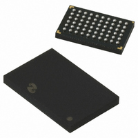
IC SRL PORT MOD BLUETOOTH 60FBGA
Manufacturer
National Semiconductor
Datasheet
1.LMX9830SMNOPB.pdf
(46 pages)
Specifications of LMX9830SM/NOPB
Frequency
2.4GHz
Data Rate - Maximum
704kbps
Modulation Or Protocol
Bluetooth v2.0, Class 2
Applications
PDA's, POS Terminals
Power - Output
0dBm
Sensitivity
-80dBm
Voltage - Supply
2.5 V ~ 3.6 V
Current - Receiving
65mA
Current - Transmitting
65mA
Data Interface
PCB, Surface Mount
Antenna Connector
PCB, Surface Mount
Operating Temperature
-40°C ~ 125°C
Package / Case
60-FBGA
Physical Interfaces
UART
Data Rate
704Kbps
Operating Temperature Range
-40°C To +125°C
Msl
MSL 4 - 72 Hours
Supply Voltage Range
1.6V To 3.6V
Frequency Max
2480MHz
Termination Type
SMD
Rohs Compliant
Yes
Filter Terminals
SMD
Frequency Min
2402MHz
Lead Free Status / RoHS Status
Lead free / RoHS Compliant
Memory Size
-
Lead Free Status / Rohs Status
Compliant
Other names
*LMX9830SM
*LMX9830SM/NOPB
LMX9830SM
*LMX9830SM/NOPB
LMX9830SM


www.national.com
T_SCLK
Note 30: Frequency, loading caps and ESR all must be considered for determining startup time.
Note 31: For reference only, must be tested on each system to accurately design POR and correctly startup system.
9.6 STARTUP SEQUENCE
During startup the LMX9830 checks the options register pins
OP3 to OP7 for configuration on operation mode, external
clock source, transport layer and available non volatile stor-
age PROM.
The different options for startup are described in Table 16.
9.6.1 Options Register
External pads in Table 16 are latched in this register at the
end of Reset. The Options register can be read by firmware
at any time.
All pads are inputs with weak on-chip pull-up/down resistors
during Reset. Resistors are disconnected at the end of
RESET_BB#.
1 = Pull-up resistor connected in application
0 = Pull-down resistor connected in application
x = Don’t care
9.6.2 Startup With External PROM Available
To be able to read out information from an external PROM the
option pins have to be set according to Table 16.
Startup sequence activities:
1.
2.
Note 32: 1/0 pull-up/down resistor connected in application.
Note 33: If OP6 is 1, must use 1k Ω pull up, If OP6 is 0, must use 10k Ω pull down.
Note 34: If OP7 is 1, must use 1k Ω pull up.
OP3
PD
x
x
x
x
From the Options registers OP6 and OP7, the LMX9830
checks if a serial PROM is available to use (ACCESS.bus
or Microwire).
If serial PROM is available, the permanent parameter
block, patch block, and non-volatile storage (NVS) are
read from it. If the BD Address is not present, enter the
BD address to be saved in the NVS. For more information
ESR (Ω)
OP4
10
25
40
50
80
PD
x
x
x
x
x
OP5
PD
x
x
x
x
x
Package Pad
OP6 (Note 33)
TABLE 16. Startup Sequence Options (Note 32)
T_RFDATA
Open (0)
Open (0)
PD
1
1
TABLE 15. ESR vs. Startup Time
Typical (Note 30), (Note 31)
OP7 (Note 34)
Open (0)
Open (0)
T_RFCE
PD
1
1
14
12
13
16
24
30
3.
4.
5.
9.6.3 Startup Without External PROM Available
The following sequence will take place if OP6 and OP7 have
been set to “No external memory” as described in Table 16.
Startup sequence activities:
1.
2.
3.
4.
5.
see Section 9.6.4 Configuring the LMX9830 Through
Transport Layer.
From the Options register OP3, OP4 and OP5, the
LMX9830 checks for clocking information and transport
layer settings. If the NVS information are not sufficient,
the LMX9830 will send the “Await Initialization” event on
the TL (Transport Layer) and wait for additional
information (see Section 9.6.3 Startup Without External
PROM Available.)
The LMX9830 compensates the UART for new BBCLK
information from the NVS.
The LMX9830 starts up the Bluetooth core.
From the Options registers OP6 and OP7, the LMX9830
checks if a serial PROM is available to use.
From the Options register OP3, OP4 and OP5, the
LMX9830 checks for clocking mode and transport layer.
The LMX9830 sends the “Await Initialization” Event on
the TL (Transport Layer) and waits for NVS configuration
commands. The configuration is finalized by sending the
“Enter Bluetooth Mode” command.
The LMX9830 compensates the UART for new BBCLK
information from the NVS.
The LMX9830 starts up the Bluetooth core.
0 BBCLK
Open (1)
Open (1)
Open (1)
Open (1)
BBCLK
BBCLK
BBCLK
BBCLK
ENV1#
PU
Comment
PD = Internal Pull-down during Reset
PU = Internal Pull-up during Reset
No serial memory
Reserved
Microwire serial memory
ACCESS.bus serial memory
Test mode
Unit
ms
ms
ms
ms
ms
Related parts for LMX9830SM/NOPB
Image
Part Number
Description
Manufacturer
Datasheet
Request
R

Part Number:
Description:
Manufacturer:
National Semiconductor
Datasheet:

Part Number:
Description:
National Semiconductor [8-Bit D/A Converter]
Manufacturer:
National Semiconductor
Datasheet:
Part Number:
Description:
National Semiconductor [Media Coprocessor]
Manufacturer:
National Semiconductor
Datasheet:
Part Number:
Description:
Digitally Controlled Tone and Volume Circuit with Stereo Audio Power Amplifier, Microphone Preamp Stage and National 3D Sound
Manufacturer:
National Semiconductor
Datasheet:
Part Number:
Description:
Digitally Controlled Tone and Volume Circuit with Stereo Audio Power Amplifier, Microphone Preamp Stage and National 3D Sound
Manufacturer:
National Semiconductor
Datasheet:
Part Number:
Description:
AC97 Rev 2 Codec with Sample Rate Conversion and National 3D Sound
Manufacturer:
National Semiconductor
Part Number:
Description:
Manufacturer:
National Semiconductor
Datasheet:
Part Number:
Description:
Manufacturer:
National Semiconductor
Datasheet:
Part Number:
Description:
General Purpose, Low Voltage, Low Power, Rail-to-Rail Output Operational Amplifiers
Manufacturer:
National Semiconductor
Datasheet:
Part Number:
Description:
8-bit 20 MSPS flash A/D converter.
Manufacturer:
National Semiconductor
Datasheet:
Part Number:
Description:
Low Noise Quad Operational Amplifier
Manufacturer:
National Semiconductor
Datasheet:
Part Number:
Description:
Quad Differential Line Receivers
Manufacturer:
National Semiconductor
Datasheet:
Part Number:
Description:
Quad High Speed Trapezoidal? Bus Transceiver
Manufacturer:
National Semiconductor
Datasheet:
Part Number:
Description:
Dual Line Receiver
Manufacturer:
National Semiconductor
Datasheet: