STEVAL-TDR028V1 STMicroelectronics, STEVAL-TDR028V1 Datasheet
STEVAL-TDR028V1
Specifications of STEVAL-TDR028V1


Related parts for STEVAL-TDR028V1


STEVAL-TDR028V1 Summary of contents
Page 1
... Efficiency: 77% typ. ■ Harmonics dBc max. ■ Gain flatness: ± 0.7 dB max. Description The STEVAL-TDR028V1 broadband power amplifier intended for FM broadcast radio transmitters over the 87.5 to 108 MHz band, using an STAC2942B gold metallized N-channel MOS field-effect transistor. The STEVAL-TDR028V1 is designed in cooperation with InnovAction S.r.l in Italy. ...
Page 2
... Surface conditions of the mounting base . . . . . . . . . . . . . . . . . . . . . . . . . . 6 4.4 Thermal interface material . . . . . . . . . . . . . . . . . . . . . . . . . . . . . . . . . . . . . 6 4.5 Seating plane . . . . . . . . . . . . . . . . . . . . . . . . . . . . . . . . . . . . . . . . . . . . . . . 6 4.6 Printed circuit board (PCB) considerations . . . . . . . . . . . . . . . . . . . . . . . . 7 4.7 Package attachment to thermal base . . . . . . . . . . . . . . . . . . . . . . . . . . . . . 7 4.7.1 4.7.2 4.8 Electrical connection . . . . . . . . . . . . . . . . . . . . . . . . . . . . . . . . . . . . . . . . . 8 4.9 Conclusion . . . . . . . . . . . . . . . . . . . . . . . . . . . . . . . . . . . . . . . . . . . . . . . . . 9 5 Revision history . . . . . . . . . . . . . . . . . . . . . . . . . . . . . . . . . . . . . . . . . . . 10 2/11 Hardware . . . . . . . . . . . . . . . . . . . . . . . . . . . . . . . . . . . . . . . . . . . . . . . . . 7 Procedure . . . . . . . . . . . . . . . . . . . . . . . . . . . . . . . . . . . . . . . . . . . . . . . . 8 Doc ID 17469 Rev 1 STEVAL-TDR028V1 ...
Page 3
... STEVAL-TDR028V1 1 Electrical data 1.1 Maximum ratings Table 2. Absolute maximum ratings Symbol OUT T STG DISS 2 Electrical characteristics + Table 3. Electrical specification Symbol Frequency Frequency range P OUT Gain P OUT ND P OUT harmonic @ harmonic @ P FL Gain flatness @ P Parameter Input power Output power Storage temperature range ...
Page 4
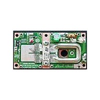
... Circuit layout and connections 3 Circuit layout and connections Figure 1. Circuit layout and connections 4/11 Doc ID 17469 Rev 1 STEVAL-TDR028V1 ...
Page 5
... STEVAL-TDR028V1 4 STAC2942B mounting recommendations 4.1 Introduction RF power transistors are amongst the highest power density devices in the semiconductor industry crucial to the reliability and performance of such devices to give additional consideration to mechanical stresses and thermal and electrical resistances within the application environment. The general purpose of this section is to provide guidelines for mechanically mounting STAC™ ...
Page 6
... PCB fabrication tolerances are such that the leads extend above the plane defined by the top of the PCB; this situation is best handled with a judicious selection of solder pad preform or paste thickness slight downward bending of the transistor leads (no more than 0.01 in (0.25 mm case should the leads be 6/11 Doc ID 17469 Rev 1 STEVAL-TDR028V1 ...
Page 7
... STEVAL-TDR028V1 bent higher than the topside of the PCB, to avoid shear stresses which could cause damage to the interface between the lead and the package body. ● Care should be taken to factor in the thickness of the TIM used, which is equivalent to increasing the seating plane dimension. ...
Page 8
... In such cases, solder-wells or a solder- moat around the perimeter of the flange should be considered, to provide a region for excess solder to flow. 8/11 Doc ID 17469 Rev 1 STEVAL-TDR028V1 ...
Page 9
... STEVAL-TDR028V1 4.9 Conclusion This section has provided a set of guidelines to be considered for the proper attachment of the STAC244B and STAC265B packages in the majority of applications. In most cases, these recommendations are expected to result in reliable mechanical, electrical, and thermal performance. In terms of thermal resistance, these recommendations should provide an exceptionally low thermal resistance between the transistor case and the mounting base (R order of 0.05 ° ...
Page 10
... Revision history 5 Revision history Table 4. Document revision history Date 03-Jun-2010 10/11 Revision 1 Initial release. Doc ID 17469 Rev 1 STEVAL-TDR028V1 Changes ...
Page 11
... STEVAL-TDR028V1 Information in this document is provided solely in connection with ST products. STMicroelectronics NV and its subsidiaries (“ST”) reserve the right to make changes, corrections, modifications or improvements, to this document, and the products and services described herein at any time, without notice. All ST products are sold pursuant to ST’s terms and conditions of sale. ...