STEVAL-TDR028V1 STMicroelectronics, STEVAL-TDR028V1 Datasheet - Page 5
STEVAL-TDR028V1
Manufacturer Part Number
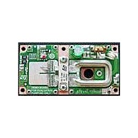
STEVAL-TDR028V1
Description
BOARD DEMO RF PWR AMP STAC2942B
Manufacturer
STMicroelectronics
Type
Power Amplifierr
Specifications of STEVAL-TDR028V1
Contents
Board
Maximum Operating Temperature
+ 70 C
Operating Supply Voltage
48 V
Product
Power Management Development Tools
For Use With/related Products
STAC2942B
Lead Free Status / RoHS Status
Lead free / RoHS Compliant
Other names
497-10763


STEVAL-TDR028V1
4
4.1
4.2
STAC2942B mounting recommendations
Introduction
RF power transistors are amongst the highest power density devices in the semiconductor
industry. It is crucial to the reliability and performance of such devices to give additional
consideration to mechanical stresses and thermal and electrical resistances within the
application environment.
The general purpose of this section is to provide guidelines for mechanically mounting
STAC™ boltdown packages so as to minimize stress and resistance. More specifically,
attention is paid to the STAC244B and STAC265B package families which are used for
various VDMOS and LDMOS products.
Heatsink selection and preparation
The choice of heatsinking system depends on the specific device and application needs;
this decision results in the total power dissipation capability for the amplifier assembly.
In most cases, the power transistor may be mounted directly to a typical heatsink, such as a
low-cost, extruded aluminum heatsink with fins. Such a system has good thermal and
electrical properties for most operating conditions.
In cases of higher power dissipation, additional spreading of the thermal flux can be
managed with a copper core heat-spreading layer between the transistor and heatsink.
Such a system can be designed for excellent thermal and electrical properties for the most
demanding operating conditions.
When the operating conditions of the device are such that the dissipated power is low, for
example in low duty cycle or back-off power conditions, a basic thermal core layer without
fins may be all that is required to maintain a high MTTF or adherence to a maximum rating.
The preferred material layer to which the package is attached is OFHC (UNS C10100)
copper, but may also be a lower quality copper or aluminum as required by detailed
application needs. Based on requirements for typical applications, the thickness of this layer
is expected to be:
●
●
●
Since holes are to be tapped into the thermal core layer for device attachment, it is advised
to drill and tap through the entire layer whenever possible. For the recommended screws,
the minimum tapped hole depth should be 0.12 in (3.0 mm).
By design, the STAC244B and STAC265B package family do not require complex heatsink
or core preparation, such as channels, pockets, cavities, etc., assuming a typical PCB
thickness is selected for the application.
Min.: 0.12 in (3.0 mm)
Typ.: 0.22 in (5.6 mm)
Max.: 0.32 in (8.1 mm)
Doc ID 17469 Rev 1
STAC2942B mounting recommendations
5/11
Related parts for STEVAL-TDR028V1
Image
Part Number
Description
Manufacturer
Datasheet
Request
R

Part Number:
Description:
BOARD EVAL FOR ST802RT1
Manufacturer:
STMicroelectronics
Datasheet:

Part Number:
Description:
EVAL BOARD 100 BASE T
Manufacturer:
STMicroelectronics
Datasheet:

Part Number:
Description:
BOARD ELECT FISCAL CASH REGISTER
Manufacturer:
STMicroelectronics
Datasheet:
Part Number:
Description:
BOARD EVAL FOR ST802RT1A
Manufacturer:
STMicroelectronics
Datasheet:

Part Number:
Description:
2 kW/100 V RF demonstration board for 3 T MRI based on the STAC4932B
Manufacturer:
STMICROELECTRONICS [STMicroelectronics]
Datasheet:

Part Number:
Description:
BOARD EVAL FOR MEMS SENSORS
Manufacturer:
STMicroelectronics
Datasheet:
Part Number:
Description:
EVALBOARD/STEVAL-ISV014V1
Manufacturer:
STMicroelectronics

Part Number:
Description:
BOARD EVAL FOR VACUUM CLEANER
Manufacturer:
STMicroelectronics
Datasheet:

Part Number:
Description:
KIT DEV STARTER ST10F276Z5
Manufacturer:
STMicroelectronics
Datasheet:

Part Number:
Description:
BOARD LED CTLR/DVR STLED316S
Manufacturer:
STMicroelectronics
Datasheet:
Part Number:
Description:
STMicroelectronics [RIPPLE-CARRY BINARY COUNTER/DIVIDERS]
Manufacturer:
STMicroelectronics
Datasheet:
Part Number:
Description:
STMicroelectronics [LIQUID-CRYSTAL DISPLAY DRIVERS]
Manufacturer:
STMicroelectronics
Datasheet:
Part Number:
Description:
BOARD EVAL FOR MEMS SENSORS
Manufacturer:
STMicroelectronics
Datasheet: