STEVAL-TDR028V1 STMicroelectronics, STEVAL-TDR028V1 Datasheet - Page 7
STEVAL-TDR028V1
Manufacturer Part Number
STEVAL-TDR028V1
Description
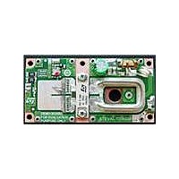
BOARD DEMO RF PWR AMP STAC2942B
Manufacturer
STMicroelectronics
Type
Power Amplifierr
Specifications of STEVAL-TDR028V1
Contents
Board
Maximum Operating Temperature
+ 70 C
Operating Supply Voltage
48 V
Product
Power Management Development Tools
For Use With/related Products
STAC2942B
Lead Free Status / RoHS Status
Lead free / RoHS Compliant
Other names
497-10763


STEVAL-TDR028V1
4.6
4.7
4.7.1
●
●
Printed circuit board (PCB) considerations
It is advisable to specify a “package-cut”, or slot, through the board and mount the transistor
directly to the heatsink for optimum performance. The dimensions for this slot should be
approximately 0.010 to 0.025 in (0.25 to 0.6 mm) larger than the outside dimensions of the
package body to ensure a good fit and to relieve stress upon the leads.
These packages were designed to be compatible with PCBs having dielectric thicknesses in
the range of 0.020 to 0.060 in (0.51 to 1.52 mm) - a wide range, covering a large scope of
applications. As a general rule, as the thickness of the PCB increases within this range, the
greater the offset dimensions for the slot should be designed.
Often, the PCB traces are slightly pulled back from the edge of the slot, which is also helpful
in reducing stress upon the leads of the device. Solder pad layouts for the transistor leads
should be designed to be as large as the circuit topology allows, but it is recommended that
pad area be at least the maximum width and remaining length of the leads (approximately
0.15 in or 3.8 mm). In most cases a border around the leads of at least 0.01 in (0.25 mm) for
solder is advised, which allows for a good solder fillet along three sides of each transistor
lead.
Package attachment to thermal base
Hardware
The recommended fastener system consists of:
●
●
The procedure begins with the application of the TIM to the back of the package, followed by
the insertion of the package into the application board. It is best to start the screws in both
tapped holes, continuing in an alternating fashion to insure the package is seated flat and
without obstructions.
To evenly distribute the pressure from the screw head/split washer combination, a flat
washer with an outer diameter no greater than 0.28 in (7.1 mm) can be inserted between the
split washer and the package body.
As a substitute for a split washer, a conical, Belleville, or wave washer can be used.
When this system is properly applied, uniform pressure with tolerance for thermal expansion
is provided. The mechanical features designed into the STAC™ boltdown package translate
the force toward the center of the package at the prescribed screw torque. Along with the
bent higher than the topside of the PCB, to avoid shear stresses which could cause
damage to the interface between the lead and the package body.
Care should be taken to factor in the thickness of the TIM used, which is equivalent to
increasing the seating plane dimension.
If the PCB is fused to the heatsink by means of a bonding film, solder layer, etc., the
corresponding thickness of this layer should be factored into the PCB thickness.
2 4UNC (or M3) Torx, hex or Phillips cap screws (one for each end of the package
body)
2 spring washers, ID=0.150” (3.81 mm) OD=0.275” (6.98 mm) t=0.015” (0.38 mm)
h=0.025” (0.62 mm)
Doc ID 17469 Rev 1
STAC2942B mounting recommendations
7/11
Related parts for STEVAL-TDR028V1
Image
Part Number
Description
Manufacturer
Datasheet
Request
R

Part Number:
Description:
BOARD EVAL FOR ST802RT1
Manufacturer:
STMicroelectronics
Datasheet:

Part Number:
Description:
EVAL BOARD 100 BASE T
Manufacturer:
STMicroelectronics
Datasheet:

Part Number:
Description:
BOARD ELECT FISCAL CASH REGISTER
Manufacturer:
STMicroelectronics
Datasheet:
Part Number:
Description:
BOARD EVAL FOR ST802RT1A
Manufacturer:
STMicroelectronics
Datasheet:

Part Number:
Description:
2 kW/100 V RF demonstration board for 3 T MRI based on the STAC4932B
Manufacturer:
STMICROELECTRONICS [STMicroelectronics]
Datasheet:

Part Number:
Description:
BOARD EVAL FOR MEMS SENSORS
Manufacturer:
STMicroelectronics
Datasheet:
Part Number:
Description:
EVALBOARD/STEVAL-ISV014V1
Manufacturer:
STMicroelectronics

Part Number:
Description:
BOARD EVAL FOR VACUUM CLEANER
Manufacturer:
STMicroelectronics
Datasheet:

Part Number:
Description:
KIT DEV STARTER ST10F276Z5
Manufacturer:
STMicroelectronics
Datasheet:

Part Number:
Description:
BOARD LED CTLR/DVR STLED316S
Manufacturer:
STMicroelectronics
Datasheet:
Part Number:
Description:
STMicroelectronics [RIPPLE-CARRY BINARY COUNTER/DIVIDERS]
Manufacturer:
STMicroelectronics
Datasheet:
Part Number:
Description:
STMicroelectronics [LIQUID-CRYSTAL DISPLAY DRIVERS]
Manufacturer:
STMicroelectronics
Datasheet:
Part Number:
Description:
BOARD EVAL FOR MEMS SENSORS
Manufacturer:
STMicroelectronics
Datasheet: