AT88RF1354-ZU Atmel, AT88RF1354-ZU Datasheet - Page 10
AT88RF1354-ZU
Manufacturer Part Number
AT88RF1354-ZU
Description
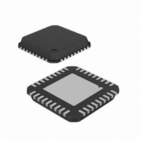
IC RF READER 13.56MHZ 36-VQFN
Manufacturer
Atmel
Datasheet
1.AT88RF1354-ZU.pdf
(48 pages)
Specifications of AT88RF1354-ZU
Frequency
13.56MHz
Features
ISO14443-B
Package / Case
36-VQFN Exposed Pad, 36-HVQFN, 36-SQFN, 36-DHVQFN
Pin Count
36
Screening Level
Industrial
Lead Free Status / RoHS Status
Lead free / RoHS Compliant
Rf Type
-
Lead Free Status / Rohs Status
Compliant


4.1.
4.1.1. V
4.1.2. V
4.1.3. V
4.1.4. V
4.1.5. V
4.1.6. QFN Package Thermal Pad [ePad]
10
Power and Ground Pin Descriptions
Supply Voltage for I/O buffers, digital, and analog circuits. V
since all digital I/O levels are referenced to V
Two V
must be placed within 3 mm of the package. A 2.2 uF capacitor should also be placed within 3 cm of the package.
Ceramic capacitors with X5R or X7R dielectric and a working voltage of 10 volts minimum should be used.
Digital ground. Ground for I/O buffers and digital circuits. For maximum performance the digital ground plane must be
separated from the analog ground plane (V
Analog ground. Ground for analog circuits. For maximum performance the V
V
V
Antenna supply voltage. Powers the transmitter and antenna drive circuits.
Two V
SRF of 32 MHz must be placed within 3 mm of
of the package. Ceramic capacitors with X5R or X7R dielectric and a working voltage of 10 volts minimum should be
used.
Antenna ground. High current return path for transmitter and antenna drive circuit current. For maximum performance
the V
circuit block.
Ground for the die substrate. Must be connected directly to the V
thermal pad must be soldered to a thermal pad on the board as described in Appendix D to dissipate heat generated in
the die.
Warning: If V
13.56 MHz Type B RF Reader Specification
SS
SS
CC
SS
SS
CC
SS
_ANT.
A [23]
_ANT [2]
_ANT [1]
ground plane at only a single point within 1 cm of pins 22 and 23. V
SS
[22]
[24]
CC
CC
_ANT ground plane should connect to V
_ANT bypass capacitors must be connected between the V
bypass capacitors must be connected between the V
injected into the receiver circuit. Likewise, if V
transmitter noise will be injected into the receiver circuit. These PCB configurations will significantly reduce
the communication performance of the reader (reducing the communication distance).
SS
, V
SS
A, V
SS
_ANT, and ePad are tied to a single monolithic ground plane, then transmitter noise will be
SS
CC
A) and the antenna ground plane (V
SS
at only a single point near the power filters at the edge of the reader
the package and a 2.2 uF capacitor must be placed within 5 mm
CC
and V
CC
CC
SS
pin and V
CC
voltage must match the microcontroller I/O voltage
digital ground plane with multiple vias. The package
CC
_ANT are tied to one monolithic power plane, then
_ANT pin and V
SS
SS
. A 15 nF capacitor with SRF of 32 MHz
SS
A should not be connected directly to
SS
A ground plane should connect to the
_ANT) by a minimum of 20 mils.
SS
_ANT. A 15 nF capacitor with
8547B–RFID–3/09
Related parts for AT88RF1354-ZU
Image
Part Number
Description
Manufacturer
Datasheet
Request
R

Part Number:
Description:
DEV KIT FOR AVR/AVR32
Manufacturer:
Atmel
Datasheet:

Part Number:
Description:
INTERVAL AND WIPE/WASH WIPER CONTROL IC WITH DELAY
Manufacturer:
ATMEL Corporation
Datasheet:
Part Number:
Description:
Low-Voltage Voice-Switched IC for Hands-Free Operation
Manufacturer:
ATMEL Corporation
Datasheet:
Part Number:
Description:
MONOLITHIC INTEGRATED FEATUREPHONE CIRCUIT
Manufacturer:
ATMEL Corporation
Datasheet:
Part Number:
Description:
AM-FM Receiver IC U4255BM-M
Manufacturer:
ATMEL Corporation
Datasheet:
Part Number:
Description:
Monolithic Integrated Feature Phone Circuit
Manufacturer:
ATMEL Corporation
Datasheet:
Part Number:
Description:
Multistandard Video-IF and Quasi Parallel Sound Processing
Manufacturer:
ATMEL Corporation
Datasheet:
Part Number:
Description:
High-performance EE PLD
Manufacturer:
ATMEL Corporation
Datasheet:
Part Number:
Description:
8-bit Flash Microcontroller
Manufacturer:
ATMEL Corporation
Datasheet:
Part Number:
Description:
2-Wire Serial EEPROM
Manufacturer:
ATMEL Corporation
Datasheet: