CTE701 3M, CTE701 Datasheet - Page 4
CTE701
Manufacturer Part Number
CTE701
Description
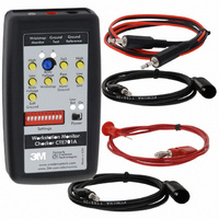
WORKSTATION MONITOR CHECKER
Manufacturer
3M
Series
ScanEM® Probesr
Type
Monitorr
Datasheet
1.CTE701.pdf
(4 pages)
Specifications of CTE701
Description/function
Workstation Monitor Checkers
For Use With/related Products
Workstation, Wrist Straps
Lead Free Status / RoHS Status
Contains lead / RoHS non-compliant
Features
-
Power Supply Type
-
Lead Free Status / Rohs Status
Lead free / RoHS Compliant
Other names
51111161982
80000919490
SCP265
XA004143203
80000919490
SCP265
XA004143203


4
Ground Resistance
Ground Resistance
Resistance, Ohms
Resistance, Ohms
Basics
For all tests make sure that:
Metal Ground
This test verifies proper operation of your monitor on metal ground monitoring as
well as EMI detection.
Settings
Ground Resistance
Ground Resistance
Ground Resistance
Setup switches allow you to set the parameters in accordance to your specification.
Metal ground impedance setting is done using dip switches 5...8.
Resistance, Ohms
Resistance, Ohms
Resistance, Ohms
Pressing a “Fail” push-button switch will result in resistance that is 1 Ohm
higher than set above, pressing the “Pass” push-button switch will result in
resistance that is 1 Ohm less. For example, if your factory is using 10 Ohms as
specification for ground impedance, then the monitor set to 10 Ohms should
pass at 9 Ohms and fail at 11 Ohms.
monitored grounds. Leave ground connection of the monitor itself con-
nected to a known good ground
the Reference Ground jack of the Checker and the alligator clip end of this
cable to a ground terminal of the monitor under test.
Monitor under test itself is properly grounded and is operational.
Disconnect all wires from the monitor under test that go to the
Connect banana end of the black grounding cable of the Checker into
Turn the Checker on.
1
2
3
4
5
6
7
8
9
10
11
12
13
14
15
16
5 5 5 5 5
1
0
1
0
1
0
1
0
1
0
1
0
1
0
1
0
Switch P
Switch P
Switch P
Switch P
Switch Position
6 6 6 6 6
1
1
0
0
1
1
0
0
1
1
0
0
1
1
0
0
osition
osition
osition
osition
7 7 7 7 7
1
1
1
1
0
0
0
0
1
1
1
1
0
0
0
0
8 8 8 8 8
1
1
1
1
1
1
1
1
0
0
0
0
0
0
0
0
Places of contact for metal grounds test for WS Aware and Ground
Master monitors. In other monitors it may vary. In all cases disconnect
monitor from monitored tool and bench grounds for the test.
E M I
E M I
E M I
E M I
E M I
The checker provides high frequency signal to test EMI detection threshold. EMI
level is set using dip switch 9 9 9 9 9 . The checker provides two different levels of high
frequency signal -- “elevated” and “normal.” In position 1 the EMI level is
“elevated,” in position 0 the level is “normal.” Pressing “High” push button
switch will result in high signal level within its range, pressing “Low” push
button will result in low signal within its range. Note that internal EMI generator
drive may be insufficient to drive extremely low load, such as 0 or 1 Ohm.
Procedure -- Metal Grounds
G1, G2
Test jack of the Checker
Make sure that the contact is good.
indicate failure (typically, red light on the monitor). A momentary “blink” of
pass light on the monitor (typically green) when the button is depressed is
acceptable.
monitor shall indicate good ground (typically green light on the monitor).
Plug banana end of red cable of the Checker into the Ground Under
Plug the thin tip of red cable into the ground terminal of your monitor.
Depress the “Fail” button on the Checker. Ground monitor shall
Depress the “Pass” Metal Ground button on the Checker. Ground
While keeping the “Pass” Metal Ground button pressed, simultaneously
Follow instructions in Basics
WS Aware CTC061
Basics
Basics
Basics
Basics section
Insert test pin into opening for the wire --
do not use screw as contact point
Ground Master CTC065-3
1...4 5...8
5