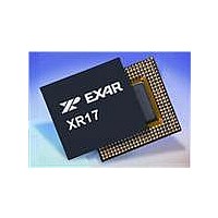
XR17V352IB113-F Exar Corporation, XR17V352IB113-F Datasheet - Page 59

XR17V352IB113-F
Manufacturer Part Number
XR17V352IB113-F
Description
IC UART PCIE 256B DUAL 113FPBGA
Manufacturer
Exar Corporation
Datasheet
1.XR17V352IB113-F.pdf
(64 pages)
Specifications of XR17V352IB113-F
Number Of Channels
2, DUART
Package / Case
113-LFBGA
Features
*
Fifo's
256 Byte
Protocol
RS485
Voltage - Supply
3.3V
With Auto Flow Control
Yes
With Irda Encoder/decoder
Yes
With False Start Bit Detection
Yes
With Modem Control
Yes
Mounting Type
Surface Mount
Data Rate
25 Mbps
Supply Current
120 mA
Maximum Operating Temperature
+ 85 C
Minimum Operating Temperature
- 40 C
Mounting Style
SMD/SMT
Operating Supply Voltage
3.3 V
No. Of Channels
2
Uart Features
Tx/Rx FIFO Counters
Supply Voltage Range
3V To 3.6V
Operating Temperature Range
-40°C To +85°C
Digital Ic Case Style
BGA
No. Of Pins
113
Rohs Compliant
Yes
Lead Free Status / RoHS Status
Lead free / RoHS Compliant
Lead Free Status / RoHS Status
Lead free / RoHS Compliant, Lead free / RoHS Compliant
Available stocks
Company
Part Number
Manufacturer
Quantity
Price
Company:
Part Number:
XR17V352IB113-F
Manufacturer:
EXAR
Quantity:
3 500
Company:
Part Number:
XR17V352IB113-F
Manufacturer:
Exar Corporation
Quantity:
10 000
Part Number:
XR17V352IB113-F
Manufacturer:
EXAR/艾科嘉
Quantity:
20 000
REV. 1.0.1
EFR[3:0]: Software Flow Control Select
Combinations of software flow control can be selected by programming these bits, as shown in
Software flow control can not be used when the Auto RS-485 Half-Duplex Direction Control feature is enabled
(FCTR[5]=1). With this feature enabled, the RTS#/DTR# output controls the direction of the half-duplex RS-
485 transceiver. The RTS#/DTR# output changes the direction of the half-duplex transceiver to the transmit
mode when data is being transmitted from the UART on the TX output. However, the RTS#/DTR# output will
remain in the receive direction if the TX FIFO is empty and the RX FIFO triggers an XON or XOFF character to
be transmitted.
Transmit FIFO level byte count from 0x00 (0 bytes) to 0xFF (255 or 256 bytes). This 8-bit register gives an
indication of the number of characters in the transmit FIFO. The FIFO level Byte count register is read only.
The user can take advantage of the FIFO level byte counter for faster data loading to the transmit FIFO, which
reduces CPU bandwidth requirements.
An 8-bit value written to this register sets the TX FIFO trigger level from 0x00 (zero) to 0xFF (255). The TX
FIFO trigger level generates an interrupt whenever the data level in the transmit FIFO falls below this preset
trigger level.
Receive FIFO level byte count from 0x00 (0 bytes) to 0xFF (255 or 256 bytes). It gives an indication of the
number of characters in the receive FIFO. The FIFO level byte count register is read only. The user can take
advantage of the FIFO level byte counter for faster data unloading from the receiver FIFO, which reduces CPU
bandwidth requirements.
4.15
4.16
4.17
EFR BIT [3]
X
X
X
0
0
1
0
1
1
0
1
0
TXCNT[7:0]: Transmit FIFO Level Counter - Read Only
TXTRG [7:0]: Transmit FIFO Trigger Level - Write Only
RXCNT[7:0]: Receive FIFO Level Counter - Read Only
EFR BIT [2]
X
X
X
0
0
0
1
1
0
1
1
0
T
ABLE
EFR BIT [1]
19: S
X
X
X
X
0
0
1
0
1
1
1
1
OFTWARE
EFR BIT [0]
0
X
X
X
X
0
0
1
1
1
1
1
F
59
LOW
HIGH PERFORMANCE DUAL PCI EXPRESS UART
C
No TX and RX flow control (default and reset)
No transmit flow control
Transmit Xon1, Xoff1
Transmit Xon2, Xoff2
Transmit Xon1 and Xon2, Xoff1 and Xoff2
No receive flow control
Receiver compares Xon1, Xoff1
Receiver compares Xon2, Xoff2
Transmit Xon1, Xoff1
Receiver compares Xon1 or Xon2, Xoff1 or Xoff2
Transmit Xon2, Xoff2
Receiver compares Xon1 or Xon2, Xoff1 or Xoff2
Transmit Xon1 and Xon2, Xoff1 and Xoff2
Receiver compares Xon1 and Xon2, Xoff1 and Xoff2
No transmit flow control
Receiver compares Xon1 and Xon2, Xoff1 and Xoff2
ONTROL
T
RANSMIT AND
F
UNCTIONS
R
ECEIVE
S
OFTWARE
F
XR17V352
LOW
Table
C
ONTROL
19.


