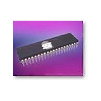
SST89V58RD2-33-C-NJE Microchip Technology, SST89V58RD2-33-C-NJE Datasheet - Page 47

SST89V58RD2-33-C-NJE
Manufacturer Part Number
SST89V58RD2-33-C-NJE
Description
IC MCU 8BIT 40KB FLASH 44PLCC
Manufacturer
Microchip Technology
Series
FlashFlex®r
Datasheet
1.SST89V54RD2-33-C-NJE.pdf
(77 pages)
Specifications of SST89V58RD2-33-C-NJE
Program Memory Type
FLASH
Program Memory Size
32KB (32K x 8)
Package / Case
44-LCC (J-Lead)
Core Processor
8051
Core Size
8-Bit
Speed
33MHz
Connectivity
EBI/EMI, SPI, UART/USART
Peripherals
Brown-out Detect/Reset, POR, WDT
Number Of I /o
36
Eeprom Size
8K x 8
Ram Size
1K x 8
Voltage - Supply (vcc/vdd)
2.7 V ~ 3.6 V
Oscillator Type
External
Operating Temperature
0°C ~ 70°C
Processor Series
SST89xxxRD
Core
8051
Data Bus Width
8 bit
Data Ram Size
1 KB
Interface Type
SPI, UART
Maximum Clock Frequency
33 MHz
Number Of Programmable I/os
32
Number Of Timers
3
Operating Supply Voltage
2.7 V to 3.6 V
Maximum Operating Temperature
+ 70 C
Mounting Style
SMD/SMT
Minimum Operating Temperature
0 C
Lead Free Status / RoHS Status
Lead free / RoHS Compliant
Data Converters
-
Lead Free Status / Rohs Status
Lead free / RoHS Compliant
Available stocks
Company
Part Number
Manufacturer
Quantity
Price
Company:
Part Number:
SST89V58RD2-33-C-NJE
Manufacturer:
Microchip Technology
Quantity:
10 000
Part Number:
SST89V58RD2-33-C-NJE
Manufacturer:
SST
Quantity:
20 000
FlashFlex MCU
SST89V54RD2/RD / SST89V58RD2/RD
8.3 Compare/Capture Modules
Each PCA module has an associated SFR with it. These
registers are: CCAPM0 for module 0, CCAPM1 for module
1, etc. Refer to “PCA Compare/Capture Module Mode Reg-
ister (CCAPMn)” on page 27 for details. The registers each
contain 7 bits which are used to control the mode each
module will operate in. The ECCF bit (CCAPMn.0 where n
= 0, 1, 2, 3, or 4 depending on module) will enable the CCF
flag in the CCON SFR to generate an interrupt when a
match or compare occurs. PWM (CCAPMn.1) enables the
pulse width modulation mode. The TOG bit (CCAPMn.2)
when set, causes the CEX output associated with the mod-
ule to toggle when there is a match between the PCA
counter and the module’s capture/compare register. When
there is a match between the PCA counter and the mod-
ule’s capture/compare register, the MATn (CCAPMn.3) and
the CCFn bit in the CCON register to be set.
TABLE
©2007 Silicon Storage Technology, Inc.
Symbol
CCAP0H PCA Module 0
CCAP0L
CCAP1H PCA Module 1
CCAP1L
CCAP2H PCA Module 2
CCAP2L
CCAP3H PCA Module 3
CCAP3L
CCAP4H PCA Module 4
CCAP4L
8-4: PCA High and Low Register Compare/Capture Modules
Description
Compare/Capture
Registers
Compare/Capture
Registers
Compare/Capture
Registers
Compare/Capture
Registers
Compare/Capture
Registers
Address
Direct
EAH
EBH
FCH
ECH
FDH
EDH
EEH
FAH
FBH
FEH
MSB
Bit Address, Symbol, or Alternative Port Function
47
Bits CAPN (CCAPMn.4) and CAPP (CCAPMn.5) deter-
mine whether the capture input will be active on a positive
edge or negative edge. The CAPN bit enables the negative
edge that a capture input will be active on, and the CAPP
bit enables the positive edge. When both bits are set, both
edges will be enabled and a capture will occur for either
transition. The last bit in the register ECOM (CCAPMn.6)
when set, enables the comparator function. Table 8-5
shows the CCAPMn settings for the various PCA functions.
There are two additional register associated with each of
the PCA modules: CCAPnH and CCAPnL. They are regis-
ters that hold the 16-bit count value when a capture occurs
or a compare occurs. When a module is used in PWM
mode, these registers are used to control the duty cycle of
the output. See Figure 8-1.
CCAP0H[7:0]
CCAP1H[7:0]
CCAP2H[7:0]
CCAP3H[7:0]
CCAP4H[7:0]
CCAP0L[7:0]
CCAP1L[7:0]
CCAP2L[7:0]
CCAP3L[7:0]
CCAP4L[7:0]
LSB
S71255-10-000
Data Sheet
RESET
Value
00H
00H
00H
00H
00H
00H
00H
00H
00H
00H
T8-4.0 1255
12/07


