KIT33912EVME Freescale Semiconductor, KIT33912EVME Datasheet
KIT33912EVME
Specifications of KIT33912EVME


Related parts for KIT33912EVME

KIT33912EVME Summary of contents
Page 1
... Freescale Semiconductor User’s Guide KIT33912EVME System Basis Chip with LIN Tranceiver Setup Instructions © Freescale Semiconductor, Inc., 2007 - 2009. All rights reserved. Document Number: KIT33912UG Rev. 2.0, 10/2009 ...
Page 2
... Opportunity/Affirmative Action Employer. Freescale and the Freescale Logo are registered in the US Patent and Trademark Office. All other product or service names are the property of their respective owners. KIT33912EVME System Basis Chip with LIN Transceiver Setup Instructions Setup Instructions, Rev. 2.0 Important Notice ...
Page 3
... SPI Status Control Registers Tab Panels ...................................................................... 17 5.5 System Status Register and SPI Status Registers ........................................................ 18 5.6 Sequence Pane ............................................................................................................. 19 Chapter 6 Embedded Slave Software KIT33912EVME System Basis Chip with LIN Tranceiver Setup Instructions, Rev. 2.0 Freescale Semiconductor Table of Contents Preface Chapter 2 Setup Instructions Chapter 4 LIN Master Control Page ...
Page 4
... CON4 The MCU Input Output Pins ............................................................................... 29 9.9 CON5 ISENSE Inputs .................................................................................................... 30 10.1 Jumper Connection ....................................................................................................... 31 Appendix A Quick Guide ........................................................................................................34 Appendix B Schematics ......................................................................................................... 35 Appendix C Placement and Layout ........................................................................................ 38 Appendix D Bill of Materials ...................................................................................................40 KIT33912EVME System Basis Chip with LIN Tranceiver Setup Instructions, Rev. 2.0 TOC-2 Chapter 10 Jumper Connection Appendices Freescale Semiconductor ...
Page 5
... Schematics - System Basis Chip .................................................................. 35 Figure B-2. Schematics - MCU ........................................................................................ 36 Figure B-3. Schematics - Loads ....................................................................................... 37 Figure C-1. Placement Top .............................................................................................. 38 Figure C-2. Copper Top ................................................................................................... 38 Figure C-3. Copper Bottom (mirrored) ............................................................................. 39 System Basis Chip with LIN tranceiver Setup Instructions, Rev. 0.0 Freescale Semiconductor List of Figures Page Number LOF-1 ...
Page 6
... KIT33912EVME System Basis Chip with LIN Tranceiver Setup Instructions, Rev. 2.0 LOF-2 Freescale Semiconductor ...
Page 7
... CON3 Output Input Terminal Definitions....................................................... 29 Table 9-7. MCU Pins not used in the Application ........................................................... 29 Table 9-8. ISENSE Connector Pin Out........................................................................... 30 Table 10-1. Jumper Connection ....................................................................................... 31 Table D-1. Bill of Materials .............................................................................................. 40 KIT33912EVME System Basis Chip with LIN Tranceiver Setup Instructions, Rev. 2.0 Freescale Semiconductor List of Tables Page Number LOT-1 ...
Page 8
... KIT33912EVME System Basis Chip with LIN Tranceiver Setup Instructions, Rev. 2.0 LOT-2 Freescale Semiconductor ...
Page 9
... Preface This User’s Guide provides the installation steps for the KIT33912EVME System Basis Chip with LIN Transceiver (SBCLIN) Audience This document is intended for application developers who are setting up Freescale’s KIT33912EVME System Basis Chip with LIN Transceiver. Suggested Reading Additional documentation on the FreeMASTER software may be found at ...
Page 10
... ActiveX (Internet Explorer 6.0 recommended) — monitor supporting a screen resolution of 1280x1024 recommended — one or two serial ports (COM) — CD-ROM drive — ≥ hard disk drive space KIT33912EVME System Basis Chip with LIN Tranceiver Setup Instructions, Rev. 2.0 2 Data Sheet Data Sheet Fact Sheet ...
Page 11
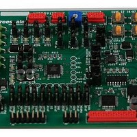
... FreeMASTER based GUI to control the devices Figure 1-1 shows the SBCLIN Evaluation Module Kit quick guide. This Evaluation Module Kit isn’t appointed for EMC tests of MC33912 device. KIT33912EVME System Basis Chip with LIN Tranceiver Setup Instructions, Rev. 2.0 Freescale Semiconductor NOTE KIT33912EVME Figure 1-1 ...
Page 12
... Results: The License Agreement box is displayed and you are prompted for further actions. 2. Clicking the Next button will start the installation program. Results: The Installation Wizard will prompt you for further actions. KIT33912EVME System Basis Chip with LIN Tranceiver Setup Instructions, Rev. 2.0 4 Figure 2-1. License Agreement Box Freescale Semiconductor ...
Page 13
... Follow the instructions given by the Installation Wizard. 4. Install the GUI. Start the GUIxx.exe installation file. Results: The Installation Wizard will prompt you for further actions. KIT33912EVME System Basis Chip with LIN Tranceiver Setup Instructions, Rev. 2.0 Freescale Semiconductor Figure 2-2. FreeMASTER Installation Setup Instructions ...
Page 14
... Setup Instructions Figure 2-3. Graphical User Interface Installation Wizard KIT33912EVME System Basis Chip with LIN Tranceiver Setup Instructions, Rev. 2.0 6 Freescale Semiconductor ...
Page 15
... For communication from the MCU to a personal computer, through FreeMASTER protocol, place Jumpers JP202 (TxD) and JP203 (RxD) in positions 1-2, which connect the MCU and the TTL / RS232 converter. 4. Configure the KIT33912EVME to an on-board control, by ensuring that Jumpers JP10 - JP16 and JP19 - JP20 are in position 1-2. 5. ...
Page 16
... Click the RETRY button to initialize all the required components. Figure 2-5. Graphical User Interface Initialization Screen 3. Default serial port setting is COM1/9600Bd. To choose a different setting, select from the main menu Project -> Options ->Comm. KIT33912EVME System Basis Chip with LIN Tranceiver Setup Instructions, Rev. 2.0 8 NOTE Freescale Semiconductor ...
Page 17
... Choose the User Helpful button to open the page with a user friendly environment and FreeMASTER communication; see Chapter 5, User Helpful Control Page Figure 2-6. Graphical User Interface Welcome Screen KIT33912EVME System Basis Chip with LIN Tranceiver Setup Instructions, Rev. 2.0 Freescale Semiconductor Setup Instructions Chapter 3, FreeMASTER Control ...
Page 18
... FreeMASTER Control Page Chapter 3 FreeMASTER Control Page 3.1 Overview The section describes basic guide to controlling the KIT33912EVME board by the FreeMASTER control page. • 3.2, Setup Instruction • 3.3, Description of the Control GUI • 3.4, SPI Registers Control/Status Array • 3.5, Pulse Width Modulation • ...
Page 19
... If the MC33912 device generates an interrupt, then a read of the Interrupt Source Register is automatic and its value is displayed on the ISR register indicators row, so that the user recognizes the interrupt occurring. KIT33912EVME System Basis Chip with LIN Tranceiver Setup Instructions, Rev. 2.0 Freescale Semiconductor Description and text below ...
Page 20
... WD ON. When there is a direct connection of the watchdog terminal to the ground, the watchdog service is disabled automatically. KIT33912EVME System Basis Chip with LIN Tranceiver Setup Instructions, Rev. 2.0 12 Figure 3-2. Control/Status Array ...
Page 21
... When all the required wake-up set-up has been done and the user presses the Stop or Sleep buttons, the status of the important registers (WUCR, HSCR, TIMCR, CFR, MCR) will be send to the device. The device will then enter one of the low power mode. KIT33912EVME System Basis Chip with LIN Tranceiver Setup Instructions, Rev. 2.0 Freescale Semiconductor Figure 3-4 ...
Page 22
... LIN Master Control Page Chapter 4 LIN Master Control Page 4.1 Overview This section shows control of the KIT33912EVME board from the control page through LIN communication protocol. • 4.2, Setup Instruction • 4.3, Description of the Control GUI • 4.4, LIN Port Control 4 ...
Page 23
... LIN Port Control KIT33912EVME board includes a LIN communication channel. For communication through LIN, stop the FreeMASTER communication port. Select COMx port in section LIN PORT:, then start communication by clicking the STOP button, see; Figure 4-2. Transmission speed is set by default to 9600 Baud. ...
Page 24
... User Helpful Control Page Chapter 5 User Helpful Control Page 5.1 Overview This section provides an overview on how to control the KIT33912EVME board from the User Helpful control page. The aim of this control environment is simplify control of the evaluation module. • 5.2, Setup Instruction • ...
Page 25
... Each SPI Status or Control Register is arranged in its own panel. Each of the sixteen panels display the possibilities for the appropriate register. Access to the other tab panels is possible by clicking on the abbreviated register names, located above and below the panel. KIT33912EVME System Basis Chip with LIN Tranceiver Setup Instructions, Rev. 2.0 Freescale Semiconductor Description Figure 5-2 ...
Page 26
... All Status Register are updated after a reset or power up. If the MC33912 device generates an interrupt, then a read of the Interrupt Source Register is automatic and its value is displayed on the Status Register array, and also on the ISR tab panel, so that the user recognizes the interrupt occurring. KIT33912EVME System Basis Chip with LIN Tranceiver Setup Instructions, Rev. 2.0 18 Section 5 ...
Page 27
... Other blocks such as Pulse Width Modulation, SPI Watchdog, Last Error Message, Graph, Wake-up Sources and Variable Watch Pane are described in Chapter 3, FreeMASTER Control KIT33912EVME System Basis Chip with LIN Tranceiver Setup Instructions, Rev. 2.0 Freescale Semiconductor and text below. Figure 5-5. Sequence Pane Page, and their functionality is similar ...
Page 28
... Generic Control is uses Free NAD values, meaning that the NAD value must be selected from the range 128 (0x80) - 255 (0xFF), and not to be interpreted as a diagnostic. For the KIT33912EVME NAD - 160 (0xA0) is used. CMD CMD is a command being sent by the master in a request to be interpreted by the slave. CMD is also used to interpret the status data in a response ...
Page 29
... A/D converter register, which is separated into two bytes. This command uses bytes S0, S1, S2 and S3. The message structure is described as follows: KIT33912EVME System Basis Chip with LIN Tranceiver Setup Instructions, Rev. 2.0 Freescale Semiconductor ...
Page 30
... S1 - hand over the reset occur S2 - hand over the interrupt state S3 - 0xFF S4 - 0xFF S5 - 0xFF 6.3 MCU Reprogram In case of loose the MCU embedded code possibility to reprogram MCU flash memory from file on CD...\GraphicalUserInterface\Project.abs.s19. KIT33912EVME System Basis Chip with LIN Tranceiver Setup Instructions, Rev. 2.0 22 Freescale Semiconductor ...
Page 31
... Embedded application” user manual. 7.2.1 WriteVariable Function Example // write to FreeMASTER variable, display error box in case of error function write_fmaster_variable(varname, value){ var succ = pcm.WriteVariable(varname, value); if (!succ) set_fmaster_err(); } KIT33912EVME System Basis Chip with LIN Tranceiver Setup Instructions, Rev. 2.0 Freescale Semiconductor FreeMASTER ActiveX Object 23 ...
Page 32
... ReadVariable Function Example // read FreeMASTER variable, display error box in case of error on success, value is returned function read_fmaster_variable(varname){ var value var succ = pcm.ReadVariable(varname); if(succ){ value = pcm.LastVariable_vValue; }else{ set_fmaster_err(); } return value; } KIT33912EVME System Basis Chip with LIN Tranceiver Setup Instructions, Rev. 2.0 24 Freescale Semiconductor ...
Page 33
... VBScript handler. The Sleep mode is aborted by a call to the Wakeup, SendMessage or RecvMessage functions. Even in the OnWakeup event, you remain in the Sleep mode until one of these three functions is called. KIT33912EVME System Basis Chip with LIN Tranceiver Setup Instructions, Rev. 2.0 Freescale Semiconductor the vData parameter (do not use 0 for VBScript arrays, as they always contain one dummy item at the end) ...
Page 34
... LastRecvDataLength; — This property retrieves the number of bytes received by the last RecvMessage() call • property: string LastErrorMsg; — This property retrieves the last error message. KIT33912EVME System Basis Chip with LIN Tranceiver Setup Instructions, Rev. 2.0 26 Freescale Semiconductor ...
Page 35
... Table 9-2. J201 Program Debug Terminal Definition Terminal Terminal Name KIT33912EVME System Basis Chip with LIN Tranceiver Setup Instructions, Rev. 2.0 Freescale Semiconductor Table 9-1 shows the terminal definitions for the J1 connector. Definition Not used Carrier detect. TXD Transmit data from MCU to PC. ...
Page 36
... LIN physical interface device (place Jumper JP205). definition. Terminal Terminal Name KIT33912EVME System Basis Chip with LIN Tranceiver Setup Instructions, Rev. 2.0 28 Definition LINRXD This terminal is the receiver output of the LIN interface which reports the state of the bus voltage to the MCU interface. ...
Page 37
... See Table 9-7. MCU Pins not used in the Application Terminal Terminal Name 1 2 KIT33912EVME System Basis Chip with LIN Tranceiver Setup Instructions, Rev. 2.0 Freescale Semiconductor Definition HS1 High Side Switch output HS1. HS2 High Side Switch output HS2. ...
Page 38
... The ISENSEH and ISENSEL terminals are the input terminals to a ground compatible differential amplifier designed to be used to sense the voltage drop over a shunt resistor. ISENSEx pins are terminated in connector CON5; see Terminal Terminal Name KIT33912EVME System Basis Chip with LIN Tranceiver Setup Instructions, Rev. 2.0 30 Definition PTD1 Not used in application. PTD3 Not used in application. PTD4 Not used in application ...
Page 39
... SPI Chip Select (CS) is connected from MCU to MC33912 2-3 position: SPI Chip Select (CS) is connected from J3 header to MC33912 Floating: (CS) is not connected KIT33912EVME System Basis Chip with LIN Tranceiver Setup Instructions, Rev. 2.0 Freescale Semiconductor Table 10-1. Jumper Connection ...
Page 40
... JP203 1-2 position: MCU output (TxD) is connected to MAX232 converter 2-3 position: LIN physical interface MCZ33661EF output (TxD) is connected to MAX232 converter Floating: SCI output of MAX232 is disconnected KIT33912EVME System Basis Chip with LIN Tranceiver Setup Instructions, Rev. 2.0 32 Table 10-1. Jumper Connection Description ...
Page 41
... Floating: LIN signal from LIN physical interface MCZ33661EF is not connected JP206 1-2 position: LIN pull-up resistor and diode are connected {Master Mode} Floating: LIN pull-up resistor and diode are disconnected {Slave Mode} KIT33912EVME System Basis Chip with LIN Tranceiver Setup Instructions, Rev. 2.0 Freescale Semiconductor Table 10-1. Jumper Connection Description ...
Page 42
... Quick Guide Appendix A Quick Guide CON2 J2 J4,J5 KIT33912EVME System Basis Chip with LIN Tranceiver Setup Instructions, Rev. 2.0 34 Appendices CON5 CON2 J3 J201 CON4 Figure A-1. Quick Guide CON2 J1 Freescale Semiconductor ...
Page 43
... Appendix B Schematics Figure B-1. Schematics - System Basis Chip KIT33912EVME System Basis Chip with LIN Tranceiver Setup Instructions, Rev. 2.0 Freescale Semiconductor Schematics 35 ...
Page 44
... Schematics KIT33912EVME System Basis Chip with LIN Tranceiver Setup Instructions, Rev. 2.0 36 Figure B-2. Schematics - MCU Freescale Semiconductor ...
Page 45
... KIT33912EVME System Basis Chip with LIN Tranceiver Setup Instructions, Rev. 2.0 Freescale Semiconductor Figure B-3. Schematics - Loads Schematics 37 ...
Page 46
... Placement and Layout Appendix C Placement and Layout KIT33912EVME System Basis Chip with LIN Tranceiver Setup Instructions, Rev. 2.0 38 Figure C-1. Placement Top Figure C-2. Copper Top Freescale Semiconductor ...
Page 47
... KIT33912EVME System Basis Chip with LIN Tranceiver Setup Instructions, Rev. 2.0 Freescale Semiconductor Figure C-3. Copper Bottom (mirrored) Placement and Layout 39 ...
Page 48
... JP204, JP205, JP206 JP10, JP11, JP12, JP13, JP14, JP15, JP16, JP17 JP18, JP19, JP20, JP202, JP203 KIT33912EVME System Basis Chip with LIN Tranceiver Setup Instructions, Rev. 2.0 40 Table D-1. Bill of Materials Part CON/3MOLEX CON/6MICROMATCH CON/18MICROMATCH CON/4MICROMATCH 330UF 100PF 4.7UF .1UF 10UF ...
Page 49
... U201 42 1 U202 U203 U204 Not refer KIT33912EVME System Basis Chip with LIN Tranceiver Setup Instructions, Rev. 2.0 Freescale Semiconductor Table D-1. Bill of Materials (continued) Part HDR_2X7 BANANA BLACK BANANA RED HDR_2X3 0 OHM 33K 2.4K 470 OHM 2 OHM 10K 39K 5.6K 330 OHM 2 ...
Page 50
... Freescale Semiconductor was negligent regarding the design or manufacture of the part. Freescale™ and the Freescale logo are trademarks of Freescale Semiconductor, Inc ...