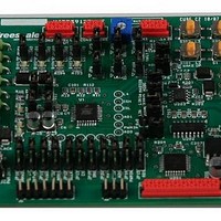
KIT33912EVME Freescale Semiconductor, KIT33912EVME Datasheet - Page 25

KIT33912EVME
Manufacturer Part Number
KIT33912EVME
Description
MCU, MPU & DSP Development Tools For MC33912 RS-232 SPI
Manufacturer
Freescale Semiconductor
Datasheet
1.KIT33912EVME.pdf
(50 pages)
Specifications of KIT33912EVME
Processor To Be Evaluated
MC33912
Interface Type
RS-232, SPI
Operating Supply Voltage
12 V
Lead Free Status / RoHS Status
Lead free / RoHS Compliant
5.4
Each SPI Status or Control Register is arranged in its own panel. Each of the sixteen panels display the possibilities for the
appropriate register. Access to the other tab panels is possible by clicking on the abbreviated register names, located above and
below the panel.
Freescale Semiconductor
Item
1. SPI Registers Tab
2. System Status Register The System Status Register is always transferred with every SPI transmission and gives a
3. SPI Status Registers
4. Pulse Width Modulation The blue bars serve to change the frequency and duty of the PWM. Parameters are changed
5. SPI Watchdog
6. Last Error Message
7. Graph
8. Wake-up Sources
9. Variable Watch Pane
10. Back Button
1 1. Sequence Pane
Panel
SPI Status Control Registers Tab Panels
Name
KIT33912EVME System Basis Chip with LIN Tranceiver Setup Instructions, Rev. 2.0
Table 5-1. Generic Control User Helpful Page Description
The Control SPI Registers tabs give a basic view on the functionality of the MC33912 device
and allows the use of these functions. The Status SPI registers tabs show possible states of
the MC33912 device and indicate their status.
quick system status overview. It summarizes the status of the Voltage Status Register VSR,
LIN Status Register LINSR, High-Side Status Register HSSR and the Low-Side Status Regis-
ter LSSR.
System status registers indicate the state of MC33912 device.
when a user drags and releases a mouse button. Frequency range of the Pulse Width
Modulation is selectable by a drop-down menu.
These two buttons show the SPI Watchdog clear time and offer a switch off for the Watchdog
clear routine.
If in communication an error occurs, then the error message is shown in the first white area.
If the user chooses one of the wake-up capabilities and the wake-up event isn’t configured
correctly, then user is given a notice on what to change to configure the wake-up properly. This
message is shown in second white area.
If a reset condition is detected, then the user is warned and the control page reverts to the
default state and the reset flag is displayed in the third white area.
The Graph indicator shows analogue voltage from the ADOUT0 and ADOUT1 outputs. The
blue line indicates the voltage on the current sense input in mV, and the blue label calculates
the current through the resistor connected to these inputs. A second line shows the variable in
accordance with the Multiplexer Control Register MUXCR. The actual source of the voltage is
displayed in the red caption of the Graph, and the appropriate axis is readjusted to the actual
units.
The section shows three wake-up sources and helps the user to correctly set-up one of the
wake-up events.
The Variable Watch Pane displays the variables assigned to the watch. It displays the current
variable values and allows user to change them (if enabled in the variable definition). See
FMASTXXX.pdf document available at http://www.freescale.com.
Clicking the Back button will open the Welcome screen.
The Sequence Pane allows control in executing the command sequence.
Figure 5-2. Status Register Tab Panel
Description
User Helpful Control Page
17


