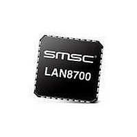
LAN8700C-AEZG-TR SMSC, LAN8700C-AEZG-TR Datasheet - Page 30

LAN8700C-AEZG-TR
Manufacturer Part Number
LAN8700C-AEZG-TR
Description
Ethernet ICs Hi Perform Ethernet PHY
Manufacturer
SMSC
Type
Single Chipr
Datasheet
1.LAN8700C-AEZG.pdf
(80 pages)
Specifications of LAN8700C-AEZG-TR
Ethernet Connection Type
10 Base-T, 100 Base-TX
Minimum Operating Temperature
- 40 C
Mounting Style
SMD/SMT
Product
Ethernet Transceivers
Number Of Transceivers
1
Standard Supported
IEEE 802.3ab
Data Rate
10 Mbps or 100 Mbps
Supply Voltage (max)
3.6 V
Supply Voltage (min)
3 V
Supply Current (max)
39 mA, 81.6 mA
Maximum Operating Temperature
+ 85 C
Package / Case
QFN EP
Lead Free Status / RoHS Status
Lead free / RoHS Compliant
Available stocks
Company
Part Number
Manufacturer
Quantity
Price
Company:
Part Number:
LAN8700C-AEZG-TR
Manufacturer:
TOSHIBA
Quantity:
24 000
Company:
Part Number:
LAN8700C-AEZG-TR
Manufacturer:
SMSC
Quantity:
1 881
Part Number:
LAN8700C-AEZG-TR
Manufacturer:
SMSC
Quantity:
20 000
Revision 2.2 (12-04-09)
4.9
4.9.1
4.9.2
The Auto-MDIX function can be disabled through an internal register.
One feature of the flexPWR technology is the ability to configure the internal 1.8V regulator off. When
the regulator is disabled, external 1.8V must be supplied to VDD_CORE. This makes it possible to
reduce total system power, since an external switching regulator with greater efficiency than the
internal linear regulator may be used to provide the +1.8V to the PHY circuitry.
Disable the Internal +1.8V Regulator
To disable the +1.8V internal regulator, a pullup strapping resistor (see
Configuration Resistors,” on page
after both VDDIO and VDDA are within specification, the PHY will sample the RXCLK/REGOFF pin to
determine if the internal regulator should turn on. If the pin is sampled at a voltage greater than V
then the internal regulator is disabled, and the system must supply +1.8V to the VDD_CORE pin. The
voltage at VDD33 must be at least 2.64V (0.8 * 3.3V) before voltage is applied to VDD_CORE. As
described in
the internal regulator is enabled and the system does not supply +1.8V to the VDD_CORE pin.
When the +1.8V internal regulator is disabled, a 0.1uF capacitor must be added at the VDD_CORE
pin and placed close to the PHY to decouple the external power supply.
Enable the Internal +1.8V Regulator
The 1.8V for VDD_CORE is supplied by the on-chip regulator unless the PHY is configured for
regulator off mode using the RX_CLK/REGOFF pin as described in
internal +1.8V regulator is enabled when the RXCLK/REGOFF pin is floating. As shown in
an internal pull-down resistor straps the regulator on if the RXCLK/REGOFF pin is floating.
During VDDIO and VDDA power-on, if the RXCLK/REGOFF pin is sampled below V
+1.8V regulator will turn on and operate with power from the VDD33 pin.
When using the internal linear regulator, a 4.7uF bypass capacitor with ESR < 1ohm and a 0.1uF
capacitor must always be added to VDD_CORE and placed close to the PHY to ensure stability of the
internal regulator.
Internal +1.8V Regulator Disable
Figure 4.4 Direct Cable Connection vs. Cross-over Cable Connection.
Section
4.9.2, when the RXCLK/REGOFF pin is left floating or connected to VSS, then
±15kV ESD Protected MII/RMII 10/100 Ethernet Transceiver with HP Auto-MDIX Support and flexPWR
DATASHEET
32) is connected from RXCLK/REGOFF to VDDIO. At power-on,
30
Section
Table 4.3, “Boot Strapping
SMSC LAN8700/LAN8700i
4.9.1. By default, the
IL
®
Technology in a Small Footprint
, then the internal
Table
Datasheet
7.11,
IH
,


