PVZ2A103C04R00 Murata, PVZ2A103C04R00 Datasheet - Page 41
PVZ2A103C04R00
Manufacturer Part Number
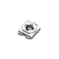
PVZ2A103C04R00
Description
Trimmer Resistors - SMD 10Kohms Open 2mm Carbon
Manufacturer
Murata
Type
Trimming Potentiometerr
Datasheets
1.PVG5A101C01R00.pdf
(89 pages)
2.PVM4A201D01R00.pdf
(55 pages)
3.PVG5A201C01R00.pdf
(90 pages)
Specifications of PVZ2A103C04R00
Resistance
10 KOhms
Power Rating
0.1 Watt (1/10 Watt)
Operating Temperature Range
- 25 C to + 85 C
Element Type
Carbon
Dimensions
2.1 mm W x 2.7 mm L x 0.8 mm H
Product
Single-Turn Trimmer Potentiometers
Termination Style
Solder Pad
Tolerance
30 %
Number Of Turns
1
Taper
Linear
Temperature Coefficient
+/- 500 PPM / C
Product Type
Single Turn
Adjustment
Top Crossed
Lead Free Status / RoHS Status
Lead free / RoHS Compliant
Available stocks
Company
Part Number
Manufacturer
Quantity
Price
Company:

Part Number:
PVZ2A103C04R00
Manufacturer:
MURATA
Quantity:
240 000
Part Number:
PVZ2A103C04R00
Manufacturer:
MURATA/村田
Quantity:
20 000


6
!Note
• This PDF catalog is downloaded from the website of Murata Manufacturing co., ltd. Therefore, it’s specifications are subject to change or our products in it may be discontinued without advance notice. Please check with our
• This PDF catalog has only typical specifications because there is no space for detailed specifications. Therefore, please approve our product specifications or transact the approval sheet for product specifications before ordering.
sales representatives or product engineers before ordering.
!Note
1. Store in temperatures of -10 to +40 deg. C and
2. Do not store in or near corrosive gases.
3. Use within six months after delivery.
4. Open the package just before using.
5. Do not store under direct sunlight.
6. If you use the trimmer potentiometer in an
1. When using with partial load (rheostat), minimize
2. The maximum input voltage to a trimmer
3. The maximum input current to a trimmer
1. Soldering
2. Mounting
40
PVG5/PV01 Series Notice
(1) Soldering condition
(2) Cannot be soldered using the flow soldering
(3) The soldering iron should not come in contact
(4) Insufficient amounts of solder can lead to
(1) Use our standard land dimension. Excessive land
(2) Do not apply excessive force (preferably 9.8N
(3) Do not warp and/or bend PC board to prevent
Notice (Operating and Storage Conditions)
relative humidity of 30-85%RH.
environment other than listed below, please
consult with a Murata factory representative prior
to using.
The trimmer potentiometer should not be used under
the following environmental conditions:
Notice (Rating)
the power depending on the resistance value.
potentiometer should not exceed (P
maximum operating voltage, whichever is smaller.
potentiometer should not exceed (P/R)^1/2 or the
allowable wiper current, whichever is smaller.
Notice (Soldering and Mounting)
Refer to the temperature profile.
If the soldering conditions are not suitable,
e.g., excessive time and/or excessive
temperature, the trimmer capacitor may deviate
from the specified characteristics.
method. If you use the flow soldering method,
the trimmer potentiometer may not function.
with the case of the trimmer potentiometer. If
such contact does occur, the trimmer
potentiometer may be damaged.
insufficient soldering strength on PCB.
Excessive amounts of solder may cause bridging
between the terminals.
area causes displacement due to the effect of
the surface tension of the solder. Insufficient
land area leads to insufficient soldering strength
of the chip.
(Ref.; 1kgf) max.), when the trimmer
potentiometer is mounted to the PCB.
trimmer potentiometer from breakage.
• Please read rating and !CAUTION (for storage, operating, rating, soldering, mounting and handling) in this catalog to prevent smoking and/or burning, etc.
• This catalog has only typical specifications because there is no space for detailed specifications. Therefore, please approve our product specifications or transact the approval sheet for product specifications before ordering.
•
R)^1/2 or the
3. Cleaning
If the trimmer potentiometer is cleaned by other
conditions, the trimmer potentiometer may be damaged.
(1) Corrosive gaseous atmosphere
(2) In liquid
(3) Dusty/dirty atmosphere
(4) Direct sunlight
(5) Static voltage nor electric/magnetic fields
(6) Direct sea breeze
(7) Other variations of the above
(4) In chip placers, the recommended size of the
(1) Isopropyl-alcohol and Ethyl-alcohol are
(2) The total cleaning time by cold dipping, vapor
(3) For ultra-sonic cleaning, the available
condition is as follows.
(Ex. Chlorine gas, Hydrogen sulfide gas, Ammonia
gas, Sulfuric acid gas, Nitric oxide gas, etc.)
(Ex. Oil, Medical liquid, Organic solvent, etc.)
cylindrical pick-up nozzle should be outer
dimension 4.0mm dia. and inner dimension 2.0mm
dia.
applicable solvents for cleaning. If you use any
other types of solvents, please consult with a
Murata factory representative prior to using.
and ultrasonic washing (conditions as below)
method should be less than 3 minutes.
Due to the ultra-sonic cleaning equipment's
peculiar self-resonance point and that the
cleaning compatibility usually depends on the jig
construction and/or the cleaning condition such
as the depth of immersion, please check the
cleaning equipment to determine the suitable
conditions.
>Power: 600W (67 liter) max.
>Frequency: 28kHz
>Temperature: Ambient temperature
R50E.pdf
05.9.9
Related parts for PVZ2A103C04R00
Image
Part Number
Description
Manufacturer
Datasheet
Request
R

Part Number:
Description:
Murata Microblower 20x20 DCDC Driver Board - Samples Only
Manufacturer:
Murata
Part Number:
Description:
357-036-542-201 CARDEDGE 36POS DL .156 BLK LOPRO
Manufacturer:
Murata
Datasheet:
Part Number:
Description:
Manufacturer:
Murata
Datasheet:
Part Number:
Description:
Manufacturer:
Murata
Datasheet:
Part Number:
Description:
Manufacturer:
Murata
Datasheet:
Part Number:
Description:
Manufacturer:
Murata
Datasheet:
Part Number:
Description:
Manufacturer:
Murata
Datasheet:
Part Number:
Description:
Manufacturer:
Murata
Datasheet:
Part Number:
Description:
Manufacturer:
Murata
Datasheet:
Part Number:
Description:
BLM21BD751SN1On-Board Type (DC) EMI Suppression Filters
Manufacturer:
Murata
Datasheet:
Part Number:
Description:
BLM15AG100SN1On-Board Type (DC) EMI Suppression Filters
Manufacturer:
Murata
Datasheet:
Part Number:
Description:
NFE31PT222Z1E9On-Board Type (DC) EMI Suppression Filters
Manufacturer:
Murata
Datasheet:
Part Number:
Description:
Chip Coil
Manufacturer:
Murata
Datasheet:
Part Number:
Description:
Chip Coil
Manufacturer:
Murata
Datasheet: