H5CX-A11-DN DC12-24/AC24 Omron, H5CX-A11-DN DC12-24/AC24 Datasheet - Page 20
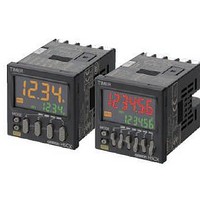
H5CX-A11-DN DC12-24/AC24
Manufacturer Part Number
H5CX-A11-DN DC12-24/AC24
Description
Stopwatches / Timers 11-PIN RELAY OUT Multi-Fnctn
Manufacturer
Omron
Datasheet
1.Y92P-CXT4B.pdf
(44 pages)
Specifications of H5CX-A11-DN DC12-24/AC24
Timing Range
0.001 s to 9999 Hrs
Supply Voltage
12 V to 24 V
Current Rating (max)
100 mA
Display Type
4 Digit LCD Backlight
Product
Digital Timer
Termination Style
Plug In
Lead Free Status / RoHS Status
Lead free / RoHS Compliant
Other names
DC1224/AC24 H5CXA11DN H5CXA11DNDC1224/AC24


20
H5CX-A@-N/-L@-N
Timer
Timing Charts
Operating Procedures for Timer Function
Models without Instantaneous Contact Outputs
The gate input is not included in the H5CX-L8@ models.
Mode A: Signal ON delay 1 (Timer resets when power comes ON.)
Basic operation
* Start signal input is disabled during timing.
Timing starts when the start signal goes ON.
While the start signal is ON, the timer starts when the
power comes ON or when the reset input goes OFF.
The control output is controlled using a sustained or
one-shot time period.
Note: Output is instantaneous when setting is 0.
Mode A-1: Signal ON delay 2 (Timer resets when power comes ON.)
Basic operation
Timing starts when the start signal goes ON, and
resets when the start signal goes OFF.
While the start signal is ON, the timer starts when the
power comes ON or when the reset input goes OFF.
The control output is controlled using a sustained or
one-shot time period.
Note: Output is instantaneous when setting is 0.
Mode A-2: Power ON delay 1 (Timer resets when power comes ON.)
Basic operation
Timing starts when the reset input goes OFF.
The start signal disables the timing function (i.e.,
same function as the gate input).
The control output is controlled using a sustained or
one-shot time period.
Note: Output is instantaneous when setting is 0.
Mode A-3: Power ON delay 2 (Timer does not reset when power comes ON.)
Basic operation
Timing starts when the reset input goes OFF.
The start signal disables the timing function (i.e.,
same function as the gate input).
The control output is controlled using a sustained or
one-shot time period.
Note: Output is instantaneous when setting is 0.
Start signal
Start signal
Output
Output
Power
Output
Power
Power
Output
Power
input
input
*
Timing
Timing
Timing
Timing
Sustained
Detailed operation
Detailed operation
Detailed operation
Detailed operation
Control output
Control output
Control output
Control output
Start signal
Start signal
Start signal
Start signal
UP
DOWN
UP
DOWN
UP
DOWN
UP
DOWN
Set value
Set value
Set value
Set value
Set value
Set value
Set value
Set value
Power
Power
Reset
Reset
Power
Power
Reset
Reset
Gate
Gate
Gate
Gate
0
0
0
0
0
0
0
0
t
t
t
t
Either one-shot output or sustained output can be selected.
t
t
t