H5CX-A11-DN DC12-24/AC24 Omron, H5CX-A11-DN DC12-24/AC24 Datasheet - Page 31
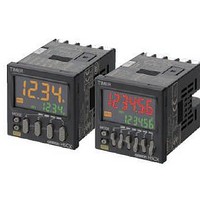
H5CX-A11-DN DC12-24/AC24
Manufacturer Part Number
H5CX-A11-DN DC12-24/AC24
Description
Stopwatches / Timers 11-PIN RELAY OUT Multi-Fnctn
Manufacturer
Omron
Datasheet
1.Y92P-CXT4B.pdf
(44 pages)
Specifications of H5CX-A11-DN DC12-24/AC24
Timing Range
0.001 s to 9999 Hrs
Supply Voltage
12 V to 24 V
Current Rating (max)
100 mA
Display Type
4 Digit LCD Backlight
Product
Digital Timer
Termination Style
Plug In
Lead Free Status / RoHS Status
Lead free / RoHS Compliant
Other names
DC1224/AC24 H5CXA11DN H5CXA11DNDC1224/AC24


Timer/Twin Timer Selection Mode (Function Selection)
Select whether the H5CX is used as a timer or a twin timer in timer/twin timer selection mode.
The H5CX is also equipped with a DIP switch monitor function, a convenient function that enables the settings of the DIP switch pins to be
confirmed using the front display.
*1. When the mode is changed to timer/twin timer selection mode, the present value is reset and output turns OFF.
*2. Setting changes made in timer/twin timer selection mode are enabled when the mode is changed to run mode.
Timing operation is not performed in timer/twin timer selection mode.
If settings are changed, the HC5X is automatically reset (present value initialized, output turned OFF).
*2
Power ON
1 s min.
+
1
*1
Timer/Twin
timer selection
DIP switch
monitor
Caution
Select either
Note: The H5CX is factory-set for timer operation.
Confirm the status of DIP switch pins 1 to 8 using the
Note: 1. This display is not supported with H5CX-L8@-N.
To change the mode to timer/twin timer selection mode,
hold down the
down. The
key is pressed first, the mode will not change.
OFF
ON
2. This display is only possible when DIP switch pin 1 (DIP switch settings
enable/disable) is set to ON (enable).
1 2 3 4 5 6 7 8
Example
keys.
tim
1
key must be pressed before the key. If the
timer operation or
1
key for 1 s min. with the
Key
twn
twin timer operation using the
key held
H5CX-A@-N/-L@-N
Indicates that DIP switch pin 8 is ON.
Indicates that DIP switch pin 7 is OFF.
Indicates that DIP switch pin 6 is ON.
Indicates that DIP switch pin 5 is OFF.
Indicates that DIP switch pin 4 is ON.
Indicates that DIP switch pin 3 is OFF.
Indicates that DIP switch pin 2 is ON.
Indicates that DIP switch pin 1 is ON.
keys.
1
Key
31