H5CX-A11-DN DC12-24/AC24 Omron, H5CX-A11-DN DC12-24/AC24 Datasheet - Page 6
H5CX-A11-DN DC12-24/AC24
Manufacturer Part Number
H5CX-A11-DN DC12-24/AC24
Description
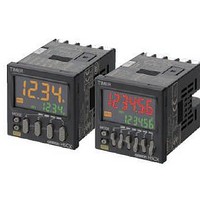
Stopwatches / Timers 11-PIN RELAY OUT Multi-Fnctn
Manufacturer
Omron
Datasheet
1.Y92P-CXT4B.pdf
(44 pages)
Specifications of H5CX-A11-DN DC12-24/AC24
Timing Range
0.001 s to 9999 Hrs
Supply Voltage
12 V to 24 V
Current Rating (max)
100 mA
Display Type
4 Digit LCD Backlight
Product
Digital Timer
Termination Style
Plug In
Lead Free Status / RoHS Status
Lead free / RoHS Compliant
Other names
DC1224/AC24 H5CXA11DN H5CXA11DNDC1224/AC24


6
H5CX-A@-N/-L@-N
Characteristics
* Refer to Life-test Curve.
Accuracy of operating time
and setting error (including
temperature and voltage
influences)
Insulation resistance
Dielectric strength
Impulse withstand voltage
Noise immunity
Static immunity
Vibration
resistance
Shock
resistance
Life
expectancy
Weight
Destruction
Malfunction
Destruction
Malfunction
Mechanical
Electrical
Power-ON start: ±0.01% ±50 ms max. (See note 1.)
Signal start: ±0.005%±0.03 ms max. (See note 1.)
Signal start for transistor output model: ±0.005%±3 ms max. (See note
1 and 2.)
If the set value is within the sensor waiting time at startup the control
output of the H5CX will not turn ON until the sensor waiting time passes.
Note: 1. The values are based on the set value.
100 MΩ min. (at 500 VDC) between current-carrying terminal and
exposed non-current-carrying metal parts, and between non-continuous
contacts
2,000 VAC, 50/60 Hz for 1 min between current-carrying metal parts and
non-current-carrying metal parts
2,000 VAC, 50/60 Hz for 1 min between power supply and input circuits
for H5CX-A11-N/-A11S-N
1,000 VAC, 50/60 Hz for 1 min between control output, power supply,
and input circuits for H5CX-@SD-N
2,000 VAC, 50/60 Hz for 1 min between control output, power supply,
and input circuits for other models
1,000 VAC, 50/60 Hz for 1 min between non-continuous contacts
3 kV (between power terminals) for 100 to 240 VAC, 1 kV for 24 VAC/12
to 24 VDC
4.5 kV (between current-carrying terminal and exposed non-current-
carrying metal parts) for 100 to 240 VAC 1.5 kV for 24 VAC/12 to 24 VDC
±1.5 kV (between power terminals) and ±600 V (between input
terminals), square-wave noise by noise simulator (pulse width: 100 ns/
1 µs, 1-ns rise)
Malfunction: 8 kV
Destruction: 15 kV
10 to 55 Hz with 0.75-mm single amplitude each in three directions for
2 h each
10 to 55 Hz with 0.35-mm single amplitude each in three directions for
10 min each
300 m/s
100 m/s
10,000,000 operations min. (under no load at 18,000 operations/h and
ambient temperature of 23
100,000 operations min. (5 A at 250 VAC, resistive load at 1,800
operations/h and ambient temperature of 23
Approx. 115 g (Timer only)
2. The value is applied for a minimum pulse width of 1 ms.
2
2
in three directions, three cycles
in three directions, three cycles
°
C)
°
C)
*
Life-test Curve (Reference
Values)
A maximum current of 0.15 A can be switched at
125 VDC (cosφ =1) and a maximum current of 0.1
A can be switched if L/R is 7 ms. In both cases, a
life of 100,000 operations can be expected.
1,000
500
100
50
10
0
AC250V cos =0.4
1
DC30V L/R=7ms
2
3
AC250V/DC30V
cos =1
4
Load current (A)
5