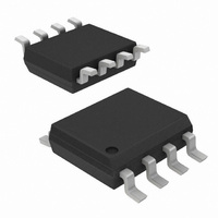
ISL12022IBZ-T7A Intersil, ISL12022IBZ-T7A Datasheet - Page 15

ISL12022IBZ-T7A
Manufacturer Part Number
ISL12022IBZ-T7A
Description
IC RTC/CALENDAR TEMP SNSR 8SOIC
Manufacturer
Intersil
Type
Clock/Calendarr
Datasheet
1.ISL12022IBZ.pdf
(28 pages)
Specifications of ISL12022IBZ-T7A
Memory Size
128B
Time Format
HH:MM:SS (12/24 hr)
Date Format
YY-MM-DD-dd
Interface
I²C, 2-Wire Serial
Voltage - Supply
1.8 V ~ 5.5 V
Operating Temperature
-40°C ~ 85°C
Mounting Type
Surface Mount
Package / Case
8-SOIC (0.154", 3.90mm Width)
Lead Free Status / RoHS Status
Lead free / RoHS Compliant
POWER SUPPLY CONTROL REGISTER (PWR_VDD)
Clear Time Stamp Bit (CLRTS)
This bit clears Time Stamp V
Stamp Battery to V
is 0 (CLRTS = 0) and the Enabled setting is 1 (CLRTS = 1).
V
These bits set the 6 trip levels for the V
that V
LVDD bit in the Status Register is set to “1”. See Table 6.
09h
FREQUENCY,
ADDR
DD
TABLE 5. FREQUENCY SELECTION OF IRQ/F
V
DD
32768
F
4096
1024
1/16
1/32
Brownout Trip Voltage BITS (V
DD
OUT
1/2
1/4
1/8
64
32
16
0
8
4
2
1
0
0
0
0
1
1
Trip2
CLRTS
has dropped below a preset level. In this event, the
7
UNITS
TABLE 6. V
6
0
Hz
Hz
Hz
Hz
Hz
Hz
Hz
Hz
Hz
Hz
Hz
Hz
Hz
Hz
Hz
Hz
DD
V
DD
5
0
Registers (TSB2V). The default setting
0
0
1
1
0
0
Trip1
FO3
4
0
0
0
0
0
0
0
0
0
1
1
1
1
1
1
1
1
DD
DD
15
3
0
TRIP LEVELS
to Battery (TSV2B) and Time
V
V
DD
DD
FO2
0
0
0
0
1
1
1
1
0
0
0
0
1
1
1
1
0
1
0
1
0
1
Trip0
2
Trip2 V
DD
DD
alarm, indicating
FO1
Trip<2:0)
OUT
DD
0
0
1
1
0
0
1
1
0
0
1
1
0
0
1
1
1
Trip1 V
VOLTAGE
PIN
2.295
2.550
2.805
3.060
4.250
4.675
TRIP
(V)
FO0
0
1
0
1
0
1
0
1
0
1
0
1
0
1
0
1
DD
0
ISL12022
Trip0
Battery Voltage Trip Voltage Register (PWR_VBAT)
This register controls the trip points for the two V
with levels set to approximately 85% and 75% of the nominal
battery level.
RESEAL BIT (RESEALB)
This is the Reseal bit for actively disconnecting V
the internal circuitry. Setting this bit allows the device to
disconnect the battery and eliminate standby current drain
while the device is unused. Once V
reset and the V
circuitry.
The application for this bit involves placing the chip on a
board with a battery and testing the board. Once the board is
tested and ready to ship, it is desirable to disconnect the
battery to keep it fresh until the board or unit is placed into
final use. Setting RESEALB = “1” initiates the battery
disconnect, and after V
again, the RESEAL bit is cleared to “0”.
BATTERY LEVEL MONITOR TRIP BITS (VB85TP<2:0>)
Three bits select the first alarm (85% of Nominal V
the battery voltage monitor. There are total of 7 levels that could
be selected for the first alarm. Any of the of levels could be
selected as the first alarm with no reference as to nominal
Battery voltage level. See Table 8.
BATTERY LEVEL MONITOR TRIP BITS (VB75TP<2:0>)
Three bits select the second alarm (75% of Nominal V
level for the battery voltage monitor. There are total of 7 levels
that could be selected for the second alarm. Any of the of levels
could be selected as the second alarm with no reference as to
nominal Battery voltage level. See Table 9.
0Ah
ADDR 7
VB85Tp2
0
0
0
0
1
1
1
D RESEALB VB85Tp2 VB85Tp1 VB85Tp0 VB75Tp2 VB75Tp1 VB75Tp0
BAT
TABLE 8. VB85T ALARM LEVEL
6
VB85Tp1
pin is then connected to the internal
0
0
1
1
0
0
1
DD
5
power is cycled down and up
TABLE 7.
4
VB85Tp0
DD
0
1
0
1
0
1
0
is powered up, this bit is
3
ALARM TRIP
BAT
2
BAT
BATTERY
BAT
LEVEL
2.125
2.295
2.550
2.805
3.060
4.250
4.675
June 23, 2009
pin from
(V)
) level for
BAT
alarms,
FN6659.2
1
)
0


