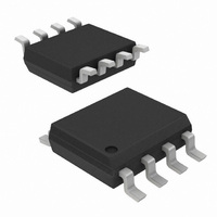
ISL12022IBZ-T7A Intersil, ISL12022IBZ-T7A Datasheet - Page 27

ISL12022IBZ-T7A
Manufacturer Part Number
ISL12022IBZ-T7A
Description
IC RTC/CALENDAR TEMP SNSR 8SOIC
Manufacturer
Intersil
Type
Clock/Calendarr
Datasheet
1.ISL12022IBZ.pdf
(28 pages)
Specifications of ISL12022IBZ-T7A
Memory Size
128B
Time Format
HH:MM:SS (12/24 hr)
Date Format
YY-MM-DD-dd
Interface
I²C, 2-Wire Serial
Voltage - Supply
1.8 V ~ 5.5 V
Operating Temperature
-40°C ~ 85°C
Mounting Type
Surface Mount
Package / Case
8-SOIC (0.154", 3.90mm Width)
Lead Free Status / RoHS Status
Lead free / RoHS Compliant
Measuring Oscillator Accuracy
The best way to analyze the ISL12022 frequency accuracy
is to set the IRQ/F
at the output of that pin on a high accuracy frequency
counter (at least 7 digits accuracy). Note that the IRQ/F
is a drain output and will require a pull-up resistor.
Using the 1.0Hz output frequency is the most convenient as
the ppm error is as expressed in Equation 8:
Other frequencies may be used for measurement but the
error calculation becomes more complex.
When the proper layout guidelines are observed, the
oscillator should start up in most circuits in less than 1s.
When testing RTC circuits, a common impulse is to apply a
scope probe to the circuit at the X2 pin (oscillator output) and
observe the waveform. DO NOT DO THIS! Although in some
cases you may see a usable waveform, due to the parasitics
(usually 10pF to ground) applied with the scope probe, there
will be no useful information in that waveform other than the
fact that the circuit is oscillating. The X2 output is sensitive to
capacitive impedance so the voltage levels and the
frequency will be affected by the parasitic elements in the
scope probe. Use the F
for the most accurate results.
Temperature Compensation Operation
The ISL12022 temperature compensation feature needs to
be enabled by the user. This must be done in a specific order
as follows.
Note that every time the BETA register is written with the
TSE bit = 1, a temperature compensation cycle is instigated
and a new correction value will be loaded into the
FATR/FDTR registers (if the temperature changed since the
last conversion).
Also note that registers 0Bh and 0Ch, the ITR0 and ALPHA
registers, should not be changed. If they must be written be
sure to write the same values that are recalled from initial
power-up. The ITR0 register may be written if the user
wishes to re-calibrate the oscillator frequency at room
ppm error
1. Read register 0Dh, the BETA register. This register
2. Bit 7 of the BETA register is the master enable control for
3. Bits 5 and 6 of the BETA register control temperature
4. Write back to register 0Dh making sure not to change the
contains the 5-bit BETA trimmed value which is
automatically loaded on initial power-up. Mask off the
5LSB’s of the value just read.
temperature sense operation. Set this to “1” to allow
continuous temperature frequency correction. Frequency
correction will then happen every 60s with V
compensation in battery-backup mode (see Table 15).
Set the values for the operation desired.
5 LSB values, and include the desired compensation
control bits.
=
F (
OUT
OUT
–
1 ) 1e6
pin for a specific frequency, and look
OUT
•
output and a frequency counter
27
DD
applied.
(EQ. 8)
OUT
ISL12022
temperature for aging or board mounting. The original
recalled value can be re-written if desired after testing.
For further information on the operation of the ISL12022 and
temperature compensated RTC’s, see Intersil Application
Note AN1389, “Using Intersil’s High Accuracy Real Time
Clock Module”.
http://www.intersil.com/data/an/AN1389.pdf
Daylight Savings Time (DST) Example
DST involves setting the forward and back times and
allowing the RTC device to automatically advance the time
or set the time back. This can be done for current year, and
future years. Many regions have DST rules that use
standard months, weeks and time of the day which permit a
pre-programmed, permanent setting.
Table 27 shows the example setup for the ISL12022.
The Enable bit (DSTE) is in the Month forward register, so
the BCD value for that register is altered with the additional
bit. The Week and Day values along with Week/Day vs Date
select bit is in the Week/Day register, so that value is also
not straight BCD. Hour and Month are normal BCD, but the
Hour doesn’t use the MIL bit since Military time PM values
are already discretely different from AM/PM time PM values.
The DST reverse setting utilizes the option to select the last
week of the month for October, which could have 4 or 5
weeks but needs to have the time change on the last
Sunday.
Note that the DSTADJ bit in the status register monitors
whether the DST forward adjustment has happened. When it
is “1”, DST forward has taken place. When it is “0”, then
either DST reverse has happened, or it has been reset either
by initial power-up or if the DSTE bit has been set to “0”.
Month Forward and DST
Enable
Week and Day Forward
and select Day/Week, not
Date
Date Forward
Hour Forward
Month Reverse
Week and Day Reverse
and select Day/Week, not
Date
Date Reverse
Hour Reverse
VARIABLE
TABLE 27. DST EXAMPLE
April
1st Week and
Sunday
not used
2am
October
Last Week and
Sunday
not used
2am
VALUE
15h
16h
17h
18h
19h
1Ah
1Bh
1Ch
REGISTER
June 23, 2009
84h
48h
00h
02h
10h
78h
00h
02h
VALUE
FN6659.2


