MORPH-IC-II FTDI, Future Technology Devices International Ltd, MORPH-IC-II Datasheet - Page 6
MORPH-IC-II
Manufacturer Part Number
MORPH-IC-II
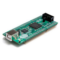
Description
MODULE USB TO FPGA
Manufacturer
FTDI, Future Technology Devices International Ltd
Type
FPGAr
Datasheet
1.MORPH-IC-II.pdf
(30 pages)
Specifications of MORPH-IC-II
Contents
Board
Lead Free Status / RoHS Status
Lead free / RoHS Compliant
For Use With/related Products
-
Other names
768-1097
Available stocks
Company
Part Number
Manufacturer
Quantity
Price


3
3.1 Morph-IC-II Block Diagram
A block diagram of the Morph-IC-II is given in Fig. 2. Morph-IC-II module can be USB powered or self
powered. The power mode is selected using the “VBUS” jumper - as indicated on the diagram below. The
FPGA can be programmed from a PC via the USB interface and the FT2232H USB bridge.
FT2232H requires a 12MHz crystal and an external EEPROM which is used to configure FT2232H.
The Altera FPGA is powered from a +3.3V regulator supply with the exception of its internal PLLs which
are powered by a +1.2V regulated supply. The power supply to the FPGA is disabled, using the MOSFET
switch, when FT2232H is in power save mode.
The I/Os of the FPGA are partitioned into 4 I/O banks. These banks each have their own power
connection. The voltage of the power connection to each bank defines the voltage level of the signals of
that bank.
The power supply to I/O bank 4 is configured differently to add more flexibility. The I/O bank 4 power
can be supplied from an external supply to the V_Bank 4 pins on J2 or from the 3V3IO net connected to
the on board regulator. This feature allows signals of different voltage levels to be used in an application
and is explained with more detail in Section 3.2.
Morph-IC-II uses a 50MHz oscillator which provides the clock source to the FPGA. Alternatively the FPGA
can be synchronised to an external clock using the CLKIN pin on connector J2.
The four connectors J1, J2, J3 and J4 provide I/O connectivity between Morph-IC-II and any application
board. The connector give a total of 80 signal lines, a FIFO interface capability, power supply pins, an
external clock line and an external reset line. The JTAG interface can be accessed through the JTAG port
or J3 and J4 connectors, using an Altera Byte Blaster (or equivalent) cable and SignalTap Analyser which
is an application of Quartus II the signals of all the I/Os of the FPGA can be displayed on a PC monitor.
JUMPER
VBUS
CONNECTOR
Functional Description
VCCUSB
USB
12MHz XTAL
USB
data
VCC3V3
3.3V REG
MOSFET POWER SWTICH
USB INTERFACE
Copyright © 2010 Future Technology Devices International Limited
CONFIGURATION
Fig. 2 – Hardware Representation of the Morph-IC-II
`
FT2232H
93C56 USB
EEPROM
IC
PROGRAMMING
INTERFACE
INTERFACE
TRANSFER
OSCILLATOR
DATA
50MHz
VCCSW
CLOCK
INT
CYCLONE TWO
EP2C5F256C8N
ALTERA
1.2V REG
3.3V REG
FPGA
PORT
JTAG
1.2DV
V_BANK4
CLOCK
EXT
3V3IO
Document Reference No.: FT_000198
BANK4_IO
V_Bank4
VCCUSB
IO
VCCSW
3V3IO
3V3IO
Clearance No.: FTDI#
1
1 2
2
17 18
29 30
MORPH-IC-II Datasheet
J1
J3
IO CONNECTORS
IO
BANK4_IO
V_Bank4
3V3IO
JTAG
IO
Version 1.04
17 18
29 30
14
J4
J2
IO
5
164
Related parts for MORPH-IC-II
Image
Part Number
Description
Manufacturer
Datasheet
Request
R

Part Number:
Description:
IC USB TO SERIAL UART 32-QFN
Manufacturer:
FTDI, Future Technology Devices International Ltd

Part Number:
Description:
IC USB HOST CTLR VINCULUM 48LQFP
Manufacturer:
FTDI, Future Technology Devices International Ltd
Datasheet:

Part Number:
Description:
IC USB HOST VINCULUM-II 32QFN
Manufacturer:
FTDI, Future Technology Devices International Ltd
Datasheet:
Part Number:
Description:
IC USB HOST VINCULUM-II 32LQFN
Manufacturer:
FTDI, Future Technology Devices International Ltd
Datasheet:
Part Number:
Description:
IC USB HOST VINCULUM-II 48QFN
Manufacturer:
FTDI, Future Technology Devices International Ltd
Datasheet:
Part Number:
Description:
IC USB HOST VINCULUM-II 32LQFN
Manufacturer:
FTDI, Future Technology Devices International Ltd
Datasheet:
Part Number:
Description:
IC USB HOST VINCULUM-II 32QFN
Manufacturer:
FTDI, Future Technology Devices International Ltd
Datasheet:
Part Number:
Description:
IC USB HOST VINCULUM-II 48LQFP
Manufacturer:
FTDI, Future Technology Devices International Ltd
Datasheet:
Part Number:
Description:
IC USB HOST VINCULUM-II 48LQFP
Manufacturer:
FTDI, Future Technology Devices International Ltd
Datasheet:
Part Number:
Description:
IC USB HOST VINCULUM-II 48QFN
Manufacturer:
FTDI, Future Technology Devices International Ltd
Datasheet:
Part Number:
Description:
IC USB HOST CTLR VINCULUM 64QFN
Manufacturer:
FTDI, Future Technology Devices International Ltd
Datasheet:

Part Number:
Description:
IC USB HOST CTLR VINCULUM 64LQFP
Manufacturer:
FTDI, Future Technology Devices International Ltd
Datasheet:
Part Number:
Description:
IC USB HOST VINCULUM-II 64LQFP
Manufacturer:
FTDI, Future Technology Devices International Ltd
Datasheet:
Part Number:
Description:
IC USB HOST VINCULUM-II 64QFN
Manufacturer:
FTDI, Future Technology Devices International Ltd
Datasheet:

Part Number:
Description:
IC USB TO PARALLEL FIFO 28-SSOP
Manufacturer:
FTDI, Future Technology Devices International Ltd
Datasheet: