MORPH-IC-II FTDI, Future Technology Devices International Ltd, MORPH-IC-II Datasheet - Page 9
MORPH-IC-II
Manufacturer Part Number
MORPH-IC-II
Description
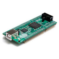
MODULE USB TO FPGA
Manufacturer
FTDI, Future Technology Devices International Ltd
Type
FPGAr
Datasheet
1.MORPH-IC-II.pdf
(30 pages)
Specifications of MORPH-IC-II
Contents
Board
Lead Free Status / RoHS Status
Lead free / RoHS Compliant
For Use With/related Products
-
Other names
768-1097
Available stocks
Company
Part Number
Manufacturer
Quantity
Price


3.4 Morph-IC-II Header Connections.
Morph-IC-II‟s FPGA is connected to five connectors: J1-J4 and the JTAG Port.
J1 to J4 are used for the following functions: connecting I/Os, “self-powered” power supply, specific bank
supply voltages and clock connections.
The JTAG connector is used to scan the I/O and registers of the FPGA.
A description for each Morph-IC-II connector is given in Table 2.
The pin description of J1, J2, J3 and J4 connectors are given in Table 3, Table 4, Table 5 and Table 6.
Pin labels for these headers are also illustrated in Fig 4 and Fig 5.
Reference Designator
CN1
CN2
J1
J2
J3
J4
Copyright © 2010 Future Technology Devices International Limited
`
Table 2 – Connector Description
Name
JTAG
Port
-
-
-
-
-
JTAG Port, used to scan I/Os and registers of
the FPGA, this feature makes it possible to
probe of the signals of a FPGA.
USB Connector
40 Pin Header
40 Pin Header
24 Pin Header
24 Pin Header
Description
Document Reference No.: FT_000198
Clearance No.: FTDI#
MORPH-IC-II Datasheet
Version 1.04
8
164
Related parts for MORPH-IC-II
Image
Part Number
Description
Manufacturer
Datasheet
Request
R

Part Number:
Description:
IC USB TO SERIAL UART 32-QFN
Manufacturer:
FTDI, Future Technology Devices International Ltd

Part Number:
Description:
IC USB HOST CTLR VINCULUM 48LQFP
Manufacturer:
FTDI, Future Technology Devices International Ltd
Datasheet:

Part Number:
Description:
IC USB HOST VINCULUM-II 32QFN
Manufacturer:
FTDI, Future Technology Devices International Ltd
Datasheet:
Part Number:
Description:
IC USB HOST VINCULUM-II 32LQFN
Manufacturer:
FTDI, Future Technology Devices International Ltd
Datasheet:
Part Number:
Description:
IC USB HOST VINCULUM-II 48QFN
Manufacturer:
FTDI, Future Technology Devices International Ltd
Datasheet:
Part Number:
Description:
IC USB HOST VINCULUM-II 32LQFN
Manufacturer:
FTDI, Future Technology Devices International Ltd
Datasheet:
Part Number:
Description:
IC USB HOST VINCULUM-II 32QFN
Manufacturer:
FTDI, Future Technology Devices International Ltd
Datasheet:
Part Number:
Description:
IC USB HOST VINCULUM-II 48LQFP
Manufacturer:
FTDI, Future Technology Devices International Ltd
Datasheet:
Part Number:
Description:
IC USB HOST VINCULUM-II 48LQFP
Manufacturer:
FTDI, Future Technology Devices International Ltd
Datasheet:
Part Number:
Description:
IC USB HOST VINCULUM-II 48QFN
Manufacturer:
FTDI, Future Technology Devices International Ltd
Datasheet:
Part Number:
Description:
IC USB HOST CTLR VINCULUM 64QFN
Manufacturer:
FTDI, Future Technology Devices International Ltd
Datasheet:

Part Number:
Description:
IC USB HOST CTLR VINCULUM 64LQFP
Manufacturer:
FTDI, Future Technology Devices International Ltd
Datasheet:
Part Number:
Description:
IC USB HOST VINCULUM-II 64LQFP
Manufacturer:
FTDI, Future Technology Devices International Ltd
Datasheet:
Part Number:
Description:
IC USB HOST VINCULUM-II 64QFN
Manufacturer:
FTDI, Future Technology Devices International Ltd
Datasheet:

Part Number:
Description:
IC USB TO PARALLEL FIFO 28-SSOP
Manufacturer:
FTDI, Future Technology Devices International Ltd
Datasheet: