MORPH-IC-II FTDI, Future Technology Devices International Ltd, MORPH-IC-II Datasheet - Page 7
MORPH-IC-II
Manufacturer Part Number
MORPH-IC-II
Description
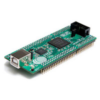
MODULE USB TO FPGA
Manufacturer
FTDI, Future Technology Devices International Ltd
Type
FPGAr
Datasheet
1.MORPH-IC-II.pdf
(30 pages)
Specifications of MORPH-IC-II
Contents
Board
Lead Free Status / RoHS Status
Lead free / RoHS Compliant
For Use With/related Products
-
Other names
768-1097
Available stocks
Company
Part Number
Manufacturer
Quantity
Price


3.2 Getting Started
3.2.1 Configuring the Jumper settings
Morph-IC-II module has two jumpers labelled VBUS and V_BANK4.
A summary of the jumper functions is given in Table 1.
NOTE: When using V_BANK4, care must be taken regarding this jumper; if there is a large enough
discrepancy between the voltage that powers an IO Bank and the logic high voltage of the signals
processed by the bank damage can occur.
3.2.2 Configuring the FPGA
The Morph-IC-II package includes a *.RBF loader programme called “MorphLd”. This programme is used
to load RBF files into the FPGA of Morph-IC-II via the USB to Passive Serial interface. These *.RBF are
synthesised HDL (VHDL or Verilog) code with additional settings for the FPGA specified by the Quartus-II
options. These files are generated when a HDL project is compiled using (suitably configured) Quartus-II
or a similar HDL compiler. Using this utility along with Quartus-II the HDL code of an application can be
compiled and exported to Morph-IC-II.
(See AN_141_MorphIO-II and MorphLd Utilities for Morph-IC-II)
1) Jumper VBUS connects USB connector pin 1 to J1-1.
2) Jumper V_BANK4 connects 3V3IO to the power supply pins of Bank 4.
A) When jumper VBUS is closed, the Morph-IC-II module is powered from the USB bus. This
B) When jumper VBUS is open, the Morph-IC-II module requires an external voltage supply of 5
A) When jumper V_BANK4 is closed, a short is formed between 3V3IO and V_BANK4. This
B) When jumper V_BANK4 is open, an external voltage supply must be applied to J2-29 and J2-
connects the VBUS power from the USB host PC to the voltage regulator input of Morph-IC-II.
This voltage regulator provides power to the following: VCC3V3, VPLL and VUSB all of which
power the FT2232H chip. This mode is known as “bus powered mode”.
Volts DC applied to J1-1. This mode is known as “self powered mode”.
connection provides 3.3 volts to I/O Bank 4 of the FPGA.
NOTE: When this jumper is closed J2-29 and J2-30 must be unconnected or
connected to a 3V3 supply (this is the case for typical MorphIC-1K application
boards).
30 to power the I/O Bank 4. The voltage level supplied should match the voltage level of the
input signals.
Jumper Name
V_BANK4
V_BANK4
VBUS
VBUS
Copyright © 2010 Future Technology Devices International Limited
`
CLOSED
CLOSED
State
OPEN
OPEN
Table 1 – Jumper Description
3.3V needs to be applied to I/O Bank 4 via J2-29
An external voltage of either 1.5V, 1.8V, 2.5V or
An external supply needs to be applied via J1-1
3.3V supplied to I/O Bank 4
Powered from the USB Bus
and J2-30
Description
Document Reference No.: FT_000198
Clearance No.: FTDI#
MORPH-IC-II Datasheet
Version 1.04
6
164
Related parts for MORPH-IC-II
Image
Part Number
Description
Manufacturer
Datasheet
Request
R

Part Number:
Description:
IC USB TO SERIAL UART 32-QFN
Manufacturer:
FTDI, Future Technology Devices International Ltd

Part Number:
Description:
IC USB HOST CTLR VINCULUM 48LQFP
Manufacturer:
FTDI, Future Technology Devices International Ltd
Datasheet:

Part Number:
Description:
IC USB HOST VINCULUM-II 32QFN
Manufacturer:
FTDI, Future Technology Devices International Ltd
Datasheet:
Part Number:
Description:
IC USB HOST VINCULUM-II 32LQFN
Manufacturer:
FTDI, Future Technology Devices International Ltd
Datasheet:
Part Number:
Description:
IC USB HOST VINCULUM-II 48QFN
Manufacturer:
FTDI, Future Technology Devices International Ltd
Datasheet:
Part Number:
Description:
IC USB HOST VINCULUM-II 32LQFN
Manufacturer:
FTDI, Future Technology Devices International Ltd
Datasheet:
Part Number:
Description:
IC USB HOST VINCULUM-II 32QFN
Manufacturer:
FTDI, Future Technology Devices International Ltd
Datasheet:
Part Number:
Description:
IC USB HOST VINCULUM-II 48LQFP
Manufacturer:
FTDI, Future Technology Devices International Ltd
Datasheet:
Part Number:
Description:
IC USB HOST VINCULUM-II 48LQFP
Manufacturer:
FTDI, Future Technology Devices International Ltd
Datasheet:
Part Number:
Description:
IC USB HOST VINCULUM-II 48QFN
Manufacturer:
FTDI, Future Technology Devices International Ltd
Datasheet:
Part Number:
Description:
IC USB HOST CTLR VINCULUM 64QFN
Manufacturer:
FTDI, Future Technology Devices International Ltd
Datasheet:

Part Number:
Description:
IC USB HOST CTLR VINCULUM 64LQFP
Manufacturer:
FTDI, Future Technology Devices International Ltd
Datasheet:
Part Number:
Description:
IC USB HOST VINCULUM-II 64LQFP
Manufacturer:
FTDI, Future Technology Devices International Ltd
Datasheet:
Part Number:
Description:
IC USB HOST VINCULUM-II 64QFN
Manufacturer:
FTDI, Future Technology Devices International Ltd
Datasheet:

Part Number:
Description:
IC USB TO PARALLEL FIFO 28-SSOP
Manufacturer:
FTDI, Future Technology Devices International Ltd
Datasheet: