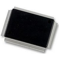
DP83865DVH National Semiconductor, DP83865DVH Datasheet - Page 42

DP83865DVH
Manufacturer Part Number
DP83865DVH
Description
10/100/1000BASE-T TRANSCEIVER, SMD
Manufacturer
National Semiconductor
Specifications of DP83865DVH
Data Rate
1000Mbps
No. Of Ports
1
Ethernet Type
IEEE 802.3u, IEEE 802.3z
Supply Current
430µA
Supply Voltage Range
2.375V To 2.625V, 3.135V To 3.465V
Operating Temperature Range
0°C To +70°C
Interface Type
GMII, MII, RGMII
Rohs Compliant
Yes
Leaded Process Compatible
No
Peak Reflow Compatible (260 C)
No
Lead Free Status / RoHS Status
Lead free / RoHS Compliant
Available stocks
Company
Part Number
Manufacturer
Quantity
Price
Company:
Part Number:
DP83865DVH
Manufacturer:
Texas Instruments
Quantity:
10 000
Company:
Part Number:
DP83865DVH/NOPB
Manufacturer:
NXP
Quantity:
1 000
Company:
Part Number:
DP83865DVH/NOPB
Manufacturer:
Texas Instruments
Quantity:
10 000
www.national.com
3.0 Configuration
The Auto-Negotiation priority resolution are as follows:
1. 1000BASE-T Full Duplex (Highest Priority)
2. 1000BASE-T Half Duplex
3. 100BASE-TX Full Duplex
4. 100BASE-TX Half Duplex
5. 10BASE-T Full Duplex
6. 10BASE-T Half Duplex (Lowest Priority)
3.3.2 Gigabit Speed Fallback
When gigabit mode is advertised, the default auto-negotia-
tion mode attempts to establish link at the highest common
denominator advertised. However, there are situations that
the cable media may not be appropriate for the gigabit
speed communication. If achieving a quality link is the
highest priority, the Speed Fallback Mode can be enabled.
The Speed Fallback Mode allows auto-negotiation to link at
the next lower speed advertised (100Mbps or 10Mbps) if
the gigabit mode fails.
There are three criteria established to initiate the gigabit
Speed Fallback.
1. Auto-negotiation failing to achieve a stable gigabit link
2. CRC error rate
3. Idle error rate
There are four basic control register bits used to configure
the Speed Fallback. Expanded register 0x1C0.3 = 1
enables the Speed Fallback mode. LED Control Register
0x13.2:0 selects the criteria for the Speed Fallback.
Bit 2, AN Bit 1, CRC Bit 0, IE
DUP
Table 34. LED Control Reg 0x13, Reg 0x1C0.3 = 1
0
0
0
0
1
1
1
1
0
0
0
0
1
1
1
1
Table 33. Speed/Duplex Selection, AN_EN = 1
Speed[1] Speed[0]
0
0
1
1
0
0
1
1
0
0
1
1
0
0
1
1
(Continued)
0
1
0
1
0
1
0
1
0
1
0
1
0
1
0
1
1000/100/10 HDX
1000/100 HDX
1000 HDX
1000/10 HDX
1000/100/10 FDX + HDX
1000/100 FDX + HDX
1000 FDX + HDX
1000/10 FDX + HDX
No Speed Fallback (SF)
SF on idle error
SF on CRC error
SF on idle and CRC
SF on failing AN
SF on AN and IE
SF on AN and CRC
SF on AN, CRC, and IE
Comments
Comments
42
The default for AN Speed Fallback is that after five tries to
achieve a stable link, the link speed will drop down to the
next lower advertised speed. The default CRC and IE
Speed Fallback is that after five link drops due to increase
error rate, the link speed drops down to the next lower
advertised speed. If during the link retry stage that the link
partner drops the link or the CAT5 cable is unplugged, the
retry counter will reload the retry count with the default
value of five.
Note that the Speed Fallback works only from gigabit mode
to 100 Mbps or 10 Mbps.
3.3.3 Gigabit Retry Forced Link
Under the situations that the cable media may not be
appropriate for the gigabit transmission, it may take exces-
sive number of retries to achieve a stable link. If achieving
a stable link is the highest priority, the Retry Forced Link
Mode can be enabled. Retry Forced Link Mode allows
auto-negotiation to force link at the highest common link
speed after five retries.
There are two criteria established to initiate the gigabit
Retry Forced Link.
1. CRC error rate
2. Idle error rate
There are three basic control register bits used to configure
the Speed Fallback and Retry Forced Link. Expanded reg-
ister 0x1C0.3 = 0 enables the Retry Forced Link mode (i.e.,
teh default mode upon power up). LED Control Register
0x13.1:0 selects the criteria for the Speed Fallback. Since
Retry Forced Link does not work when AN fails to achieve
stable link, LED Control Register 0x13.2 should be 0.
The default CRC and IE Retry Forced Link is that after five
link drops due to increase error rate, the link will be forced
at the highest advertised speed. If during the link retry
stage that the link partner drops the link or the CAT5 cable
is unplugged, the retry counter will reload the retry count
with the default value of five. Note that the retry may take
forever to achieve a forced link when link partner drops the
link or CAT5 cable is unplugged.
3.3.4 Master/Slave Resolution
If 1000BASE-T mode is selected during the priority resolu-
tion, the second goal of Auto-Negotiation is to resolve Mas-
ter/Slave configuration. The Master mode priority is given
to the device that supports multiport nodes, such as
switches and repeaters. Single node devices such as DTE
or NIC card takes lower Master mode priority.
MULTI_EN is a strapping option for advertising the Multi-
node functionality. (Table 36) In the case when both PHYs
advertise the same option, the Master/Slave resolution is
Bit 2, AN Bit 1, CRC Bit 0, IE
Table 35. LED Control Reg 0x13, Reg 0x1C0.3 = 0
0
0
0
0
0
0
1
1
0
1
0
1
No Retry Forced Link
(RFL)
RFL on idle error
RFL on CRC error
RFL on idle and CRC
Comments


