PCA9626B NXP Semiconductors, PCA9626B Datasheet - Page 9

PCA9626B
Manufacturer Part Number
PCA9626B
Description
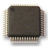
IC, LED DRIVER, RGBA, 48-LQFP
Manufacturer
NXP Semiconductors
Datasheet
1.PCA9626B118.pdf
(47 pages)
Specifications of PCA9626B
No. Of Outputs
24
Output Current
100mA
Output Voltage
40V
Input Voltage
2.3V To 5.5V
Dimming Control Type
PWM
Driver Case Style
LQFP
Switching Frequency
1MHz
Base Number
9626
Operating
RoHS Compliant
Led Driver Application
RGB Or RGBA LED Drivers, LED Status Information, Displays, Backlights
Rohs Compliant
Yes
Lead Free Status / Rohs Status
Details
Available stocks
Company
Part Number
Manufacturer
Quantity
Price
Part Number:
PCA9626B
Manufacturer:
NXP/恩智浦
Quantity:
20 000
Company:
Part Number:
PCA9626B,118
Manufacturer:
NXP Semiconductors
Quantity:
10 000
Part Number:
PCA9626B,118
Manufacturer:
NXP/恩智浦
Quantity:
20 000
Company:
Part Number:
PCA9626B/S911
Manufacturer:
FREESCALE
Quantity:
430
Part Number:
PCA9626BS
Manufacturer:
NXP/恩智浦
Quantity:
20 000
Company:
Part Number:
PCA9626BЈ¬118
Manufacturer:
PH3
Quantity:
90
NXP Semiconductors
PCA9626_2
Product data sheet
7.2 Control register
Following the successful acknowledgement of the slave address, LED All Call address or
LED Sub Call address, the bus master will send a byte to the PCA9626, which will be
stored in the Control register.
The lowest 6 bits are used as a pointer to determine which register will be accessed
(D[5:0]). The highest bit is used as Auto-Increment Flag (AIF).
This bit along with the MODE1 register bit 5 and bit 6 provide the Auto-Increment feature.
Bit 6 of the Control register is not used.
When the Auto-Increment Flag is set (AIF = logic 1), the six low order bits of the Control
register are automatically incremented after a read or write. This allows the user to
program the registers sequentially. Four different types of Auto-Increment are possible,
depending on AI1 and AI0 values of MODE1 register.
Table 3.
[1]
Remark: Other combinations not shown in
111b) are reserved and must not be used for proper device operation.
AIF + AI[1:0] = 000b is used when the same register must be accessed several times
during a single I
LED. Data is overwritten each time the register is accessed during a write operation.
AIF + AI[1:0] = 100b is used when all the registers must be sequentially accessed, for
example, power-up programming.
AIF
0
1
1
1
1
Fig 6.
AI1 and AI0 come from MODE1 register.
AI1
0
0
0
1
1
reset state = 80h
Remark: The Control register does not apply to the Software Reset I
Control register
Auto-Increment options
[1]
AI0
0
0
1
0
1
2
C-bus communication, for example, changes the brightness of a single
[1]
Function
no Auto-Increment
Auto-Increment for all registers. D[5:0] roll over to 0h after the last register
26h is accessed.
Auto-Increment for individual brightness registers only. D[5:0] roll over to
2h after the last register (19h) is accessed.
Auto-Increment for global control registers and CHASE register. D[5:0] roll
over to 1Ah after the last register (1Ch) is accessed.
Auto-Increment for individual brightness registers; global control registers
and CHASE register. D[5:0] roll over to 2h after the last register (1Ch) is
accessed.
Rev. 02 — 31 August 2009
AIF
Auto-Increment Flag
Don't care
X
D5
D4
register address
Table 3
24-bit Fm+ I
D3
D2
(AIF + AI[1:0] = 001b, 010b, 011b and
D1
002aad610
2
C-bus 100 mA 40 V LED driver
D0
2
C-bus address.
PCA9626
© NXP B.V. 2009. All rights reserved.
9 of 47


