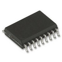
TMC222-SI TRINAMIC, TMC222-SI Datasheet - Page 26

TMC222-SI
Manufacturer Part Number
TMC222-SI
Description
IC, MOTOR CTRL/DRVR, STEPPER, SOIC-20
Manufacturer
TRINAMIC
Datasheet
1.TMC222-SI.pdf
(47 pages)
Specifications of TMC222-SI
Motor Type
Stepper
No. Of Outputs
4
Output Current
800mA
Supply Voltage Range
8V To 29V
Driver Case Style
SOIC
No. Of Pins
20
Operating Temperature Range
-40°C To +125°C
Device Type
Motor
Lead Free Status / RoHS Status
Lead free / RoHS Compliant
Available stocks
Company
Part Number
Manufacturer
Quantity
Price
Part Number:
TMC222-SI
Manufacturer:
TRINAMI
Quantity:
20 000
26
Every byte put on the SDA line must have a length of 8 bits, where the most significant bit (MSB) is
transferred first. The number of bytes that can be transmitted to the TCM222 is restricted to 8 bytes.
Each byte is followed by an acknowledge bit, which is issued by the receiving node (see figure below).
6.3 Physical Address of the circuit
The circuit must be provided with a physical address in order to discriminate this circuit from other
ones on the serial bus. This address is coded on seven bits (two bits are internally hardwired to ‘1’),
yielding the theoretical possibility of 32 different circuits on the same bus. It is a combination of four
OTP memory bits (see Table 9: OTP Memory Structure) and one hardwired address bit (pin HW).
HW must either be connected to ground or Vbat. When HW is not connected and left floating correct
functionality of the serial interface is not guaranteed. Pin HW uses the same principle to check
whether it is connected to ground or Vbat like the SWI input (see 5.1.9 External Switch).
The TMC222 supports a “general call” address. Therefore the circuit is addressable using either the
physical slave address or address “000 0000”.
With un-programmed OTP address bits (OTP_AD3=o, OTP_AD2=o, OTP_AD1=o, OTP_AD0=o) and
HW='0' (pin HW @ GND), the slave address resp. the address field of the TMC222 for reading is
11oooo01 (0xC1, 193) and for writing the slave address resp. the address field is 11oooo00 (0xC0,
192). The LSB of the address field selects read (='1') and write (='0'). With un-programmed OTP
address bits and HW='1' (pin HW @ Vbat), the slave address resp. the address field of the TMC222
for reading is 11oooo11 (0xC3, 195) and for writing the salve address resp. the address field is
11oooo10 (0xC2, 194).
6.4 Write data to TMC222
A complete datagram consists of the following: a Start condition, the slave address (7 bit), a
read/write bit (‘0’ = write, ‘1’ = read), an acknowledge bit, a number of data bytes (8 bit) each followed
by an acknowledge bit, and a Stop condition. The acknowledge bit is used to signal to the transmitter
the correct reception of the preceding byte, in this case the TMC222 pulls the SDA line low.
The TMC222 reads the incoming data at SDA with every rising edge of the SCL line. To finish the
transmission the master has to transmit a Stop condition. Some commands for the TMC222 are
supporting eight bytes of data, other commands are transmitting two bytes of data.
Copyright © 2004-2007 TRINAMIC Motion Control GmbH & Co. KG
SDA
SCL
condition
START
Figure 18: Two Wire Serial Interface - Physical Address resp. Address Field
MSB
1
AD6
'1'
Figure 17: Two Wire Serial Interface - Data Transfer
AD5
'1'
2
OTP_AD3
AD4
OTP_AD2
AD3
7
OTP_AD1
AD2
8
OTP_AD0
TMC222 DATASHEET (V. 1.06 / March 15, 2007)
AD1
HW2
AD0
ACK
9
Physical address
OTP Memory
Hardwired Bit
(Connect to 0 or 1)
1
ACK
9
condition
STOP


