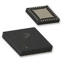
ISP1507BBS ST-Ericsson Inc, ISP1507BBS Datasheet - Page 27

ISP1507BBS
Manufacturer Part Number
ISP1507BBS
Description
IC, TRANSCEIVER, USB OTG, 32HVQFN
Manufacturer
ST-Ericsson Inc
Datasheet
1.ISP1507BBS.pdf
(81 pages)
Specifications of ISP1507BBS
Usb Type
USB Transceiver
Usb Version
2.0
Data Rate
12Mbps
No. Of Ports
1
Supply Voltage Range
3V To 3.6V
Operating Temperature Range
-40°C To +85°C
Digital Ic Case Style
QFN
No. Of Pins
32
Lead Free Status / RoHS Status
Lead free / RoHS Compliant
Available stocks
Company
Part Number
Manufacturer
Quantity
Price
Company:
Part Number:
ISP1507BBSTM
Manufacturer:
SEMIKRON
Quantity:
22
Table 10.
Table 11.
CD00222689
Product data sheet
Command
type name
Idle
Packet
transmit
Register
write
Register read 11b
DATA
1 to 0
3 to 2
5 to 4
6
7
Name
LINESTATE LINESTATE signals: For a definition of LINESTATE, see
V
RxEvent
ID
ALT_INT
BUS
TXCMD byte format
RXCMD byte format
Command code
DATA[7:6]
00b
01b
10b
state
9.5.2 RXCMD
Description and value
DATA0 — LINESTATE[0]
DATA1 — LINESTATE[1]
Encoded V
Encoded USB event signals: For an explanation of RxEvent, see
Set to the value of the ID pin.
By default, this signal is not used and is not needed in typical designs. Optionally, the link can enable
the BVALID_RISE and/or BVALID_FALL bits in the PWR_CTRL register (see
Corresponding changes in BVALID will cause an RXCMD to be sent to the link with the ALT_INT bit
asserted.
The ISP1507 communicates status information to the link by asserting DIR and sending
an RXCMD byte on the data bus. The RXCMD data byte format is given in
The ISP1507 will automatically send an RXCMD whenever there is a change in any of the
RXCMD data fields. The link must be able to accept an RXCMD at any time; including
single RXCMDs, back-to-back RXCMDs, and RXCMDs at any time during USB receive
packets when NXT is LOW. An example is shown in
refer to UTMI+ Low Pin Interface (ULPI) Specification Rev. 1.1.
An RXCMD may not be sent when exiting low-power mode or serial mode, if the interrupt
condition is removed before exiting.
Command payload
DATA[5:0]
00 0000b
00 0000b
00 XXXXb
10 1111b
XX XXXXb
10 1111b
XX XXXXb
BUS
voltage state: For an explanation of the V
Rev. 04 — 20 May 2010
Command
name
NOOP
NOPID
PID
EXTW
REGW
EXTR
REGR
Command description
No operation. 00h is the idle value of the data bus.
The link must drive NOOP by default.
Transmit USB data that does not have a PID, such
as chirp and resume signaling. The ISP1507 starts
transmitting only after accepting the next data byte.
Transmit USB packet. DATA[3:0] indicates USB
packet identifier PID[3:0].
Extended register write command (optional). The
8-bit address must be provided after the command is
accepted.
Register write command with 6-bit immediate
address.
Extended register read command (optional). The
8-bit address must be provided after the command is
accepted.
Register read command with 6-bit immediate
address.
ISP1507A; ISP1507B
Section
BUS
Figure
state, see
ULPI HS USB OTG transceiver
9.5.2.1.
Section
10. For details and diagrams,
Section
9.5.2.4.
© ST-ERICSSON 2010. All rights reserved.
Section
9.5.2.2.
Table
10.1.14).
11.
27 of 81


