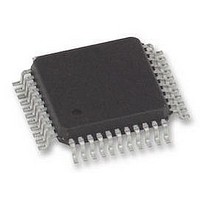
FM6124-QG Ramtron, FM6124-QG Datasheet - Page 29

FM6124-QG
Manufacturer Part Number
FM6124-QG
Description
FRAM, 24KB, EVENT DATA REC, QFP44
Manufacturer
Ramtron
Datasheet
1.FM6124-QG.pdf
(53 pages)
Specifications of FM6124-QG
Memory Size
24KB
Nvram Features
RTC
Supply Voltage Range
3V To 3.6V
Memory Case Style
QFP
No. Of Pins
44
Operating Temperature Range
-40°C To +85°C
Package / Case
QFP
Interface
I2C
Memory
RoHS Compliant
Interface Type
I2C, Serial, 2-Wire
Rohs Compliant
Yes
Access Time
100 KBPs
Operating Supply Voltage
3 V to 3.6 V
Mounting Style
SMD/SMT
Lead Free Status / Rohs Status
Details
Available stocks
Company
Part Number
Manufacturer
Quantity
Price
Company:
Part Number:
FM6124-QG
Manufacturer:
ABOV
Quantity:
3 000
Rev. 4.0 (EOL)
July 2010
0x24
0x23
P3 – P0
0x22
P11-P4
0x21
CLEAR
BF
B75F
B50F
P3 – P0
0x20
EBUFSIZE
[1:0]
ERR
DIR
Pin Event Rise/Fall A
Pin Event triggering condition
0: Pin will be triggered by a High to Low transition on the corresponding Input pin
1: Pin will be triggered by a Low to High transition on the corresponding Input pin
Pin Event Rise/Fall A
Pin Event triggering condition
0: Pin will be triggered by a High to Low transition on the corresponding Input pin
1: Pin will be triggered by a Low to High transition on the corresponding Input pin
Pin Event Interrupt B
Pin Event Interrupt activate
0: the interrupt pin will not be activated when an Event will be detected on the corresponding input pin
1: The INT pin will be activated (Low) when a Event is detected on the corresponding Input pin
Pin Event interrupt A
Writing 1 to this Bit will deactivate the INT pin, when activated by a Pin Event interrupt
Buffer Full:
Writing 1 to this bit location will make the INT to become Active then the Buffer Full condition is met
Buffer 75% Full:
Writing 1 to this bit location will make the INT to become Active then the Buffer gets 75% Full
Buffer 50% Full:
Writing 1 to this bit location will make the INT to become Active then the Buffer gets 50% Full
Pin Event Interrupt activate
0: the interrupt pin will not be activated when an Event will be detected on the corresponding input pin
1: The INT pin will be activated (Low) when a Event is detected on the corresponding Input pin
Event Recorder Control
Event Buffer and User F-RAM Sizes. Setting EBUFSIZE to a new value resets the Event Buffer.
Important: The user should disable Event Recording while resetting the Event Buffer. Setting the
EBUFSIZE bits to a different value will reset all the Event Buffer.
Error bit (RO). User can read this bit to know if they have reach the end of the Event Buffer when
reading it. Writing ERR bit has no effect.
Event Buffer Read Direction. When set to ‘1’, Read pointer (RP) will be decremented (instead of
incremented) when an event has been read out of the Event Buffer.
CLEAR
P11
P11
D7
D7
D7
D7
D7
EBUFSIZE[1:0]
P10
P10
D6
D6
D6
D6
D6
BF
EBUFSIZE
00
01
10
11
Reserved
B75F
ERR
D5
D5
D5
D5
D5
P9
P9
Max number of Events
4000
3000
2000
1000
READIR
B50F
D4
D4
D4
D4
D4
P8
P8
D3
D3
D3
D3
D3
P7
P3
P7
P3
User F-RAM size
0
8 KBytes
16 Kbytes
24 KBytes
D2
D2
D2
D2
D2
P6
P2
P6
P2
EDRCMD[3:0]
FM6124 Event Data Recorder
D1
D1
D1
D1
D1
P5
P1
P5
P1
Page 29 of 53
D0
D0
D0
D0
D0
P4
P0
P4
P0


