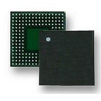
LH7A404N0F000B3 NXP Semiconductors, LH7A404N0F000B3 Datasheet - Page 30

LH7A404N0F000B3
Manufacturer Part Number
LH7A404N0F000B3
Description
MCU ARM9, LCD CTRL, SMD, LFBGA-324
Manufacturer
NXP Semiconductors
Datasheet
1.LH7A404N0F000B3.pdf
(75 pages)
Specifications of LH7A404N0F000B3
Core Size
32bit
No. Of I/o's
64
Ram Memory Size
80KB
Cpu Speed
200MHz
Oscillator Type
External Only
No. Of Timers
3
No. Of Pwm Channels
4
Digital Ic Case Style
LFBGA
Supply Voltage Range
3V
Controller Family/series
LH7A
Peripherals
ADC, DMA, RTC
Rohs Compliant
Yes
Data Bus Width
32 bit
Program Memory Type
ROMLess
Data Ram Size
80 KB
Interface Type
EBI , IrDA , JTAG , PS2 , SCI , UART , USB
Maximum Clock Frequency
200 MHz
Number Of Programmable I/os
64
Number Of Timers
3
Maximum Operating Temperature
+ 85 C
Mounting Style
SMD/SMT
Package / Case
LFBGA
Minimum Operating Temperature
- 40 C
On-chip Adc
10 bit, 9 Channel
Lead Free Status / RoHS Status
Lead free / RoHS Compliant
Available stocks
Company
Part Number
Manufacturer
Quantity
Price
Company:
Part Number:
LH7A404N0F000B3
Manufacturer:
AD
Quantity:
5 742
Company:
Part Number:
LH7A404N0F000B3,55
Manufacturer:
NXP Semiconductors
Quantity:
10 000
LH7A404
Recommended Operating Conditions for LH7A404-N0E-092-xx/LH7A404-N0F-092-xx
NOTES:
1. Core Voltage should never exceed I/O Voltage after initial power up. See “Power Supply Sequencing” on page 31.
2. Many blocks do not operate properly at speeds other than 14.7456 MHz. Some (such as USB) function only at 14.7456 MHz.
NOTE: *LH7A404-N0E-000-xx and LH7A404-N0F-000-xx only. Table 8 is representative of a typical device.
30
DC Core Supply Voltage (VDDC)
DC I/O Supply Voltage (VDD)
DC Analog Supply Voltage (VDDA)
DC A/D and TSC Supply Voltage (VDDAD)
Clock Frequency
Bus Clock Frequency
External Clock Input (XTALIN)
External Clock Input (XTALIN) Voltage
Operating Temperature
25°C
70°C
85°C
Figure 5. Temperature/Voltage/Speed Chart (LH7A404-N0E-000-xx and LH7A404-N0F-000-xx Only)
Table 8. Clock Frequency vs. Voltages (VDD) vs. Temperature*
Guaranteed values are in the Recommended Operating Conditions table.
Clock Frequency (FCLK)
Clock Period (1/FCLK)
Clock Frequency (FCLK)
Clock Period (1/FCLK)
Clock Frequency (FCLK)
Clock Period (1/FCLK)
PARAMETER
PARAMETER
255
250
245
240
235
230
225
220
215
210
205
200
25
35
213 MHz
205 MHz
200 MHz
4.69 ns
4.88 ns
5.00 ns
1.71 V
MINIMUM
45
10 MHz
14 MHz
3.14 V
1.71 V
−40°C
2.0 V
2.0 V
3.0 V
NXP Semiconductors
TEMP (
14.7456 MHz
227 MHz
220 MHz
212 MHz
4.41 ns
4.46 ns
4.72 ns
TYPICAL
55
1.80 V
2.1 V
3.3 V
1.8 V
2.1 V
3.3 V
25°C
°
C)
253 MHz
236 MHz
232 MHz
MAXIMUM NOTES
65
3.95 ns
2.36 ns
4.24 ns
266 MHz
133 MHz
1.89 V
20 MHz
1.89 V
+85°C
2.2 V
3.6 V
2.2 V
3.6 V
75
1
2
32-Bit System-on-Chip
Preliminary data sheet
85
1.89 V (+5%)
1.80 V
1.71 V (-5%)
LH7A404-182


