A1373LKB Allegro Microsystems Inc, A1373LKB Datasheet - Page 16
A1373LKB
Manufacturer Part Number
A1373LKB
Description
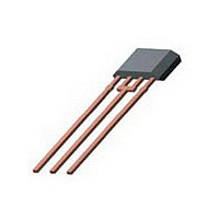
IC SENSOR HALL EFFECT PREC 3-SIP
Manufacturer
Allegro Microsystems Inc
Type
Bipolar or Unipolar, Programmabler
Datasheet
1.A1374LKB-T.pdf
(23 pages)
Specifications of A1373LKB
Sensing Range
1.75mV/G ~ 11.25mV/G
Voltage - Supply
4.5 V ~ 5.5 V
Current - Supply
10mA
Current - Output (max)
10mA
Output Type
Analog, Ratiometric
Features
High Precision
Operating Temperature
-40°C ~ 150°C
Package / Case
3-SIP
Magnetic Type
Unipolar
Operating Supply Voltage (min)
4.5V
Operating Supply Voltage (typ)
5V
Operating Supply Voltage (max)
5.5V
Output Current
10mA
Package Type
SIP
Pin Count
3
Mounting
Through Hole
Operating Temp Range
-40C to 150C
Operating Temperature Classification
Automotive
Lead Free Status / RoHS Status
Contains lead / RoHS non-compliant


A1373
A1374
Several parameters can be field-programmed. To do so, a coded
series of voltage pulses through the VOUT pin is used to set
bitfields in onboard registers. The effect on the device output can
be monitored, and the registers can be cleared and set repeatedly
until the required output results are achieved. To make the setting
permanent, bitfield-level solid state fuses are blown, and finally,
a device-level fuse is blown, blocking any further coding.
Although any programmable variable power supply can be
used to generate the pulsed waveforms, Allegro highly recom-
mends using the Allegro Sensor IC Evaluation Kit, available on
the Allegro Web site On-line Store. The manual for that kit is
available for download free of charge, and provides additional
information on programming these devices.
There are three voltage levels that must be taken into account
when programming. For purposes of explanation in this docu-
ment, the signal levels are referred to simply as high program-
ming voltage, V
PROGRAMMING PROTOCOL CHARACTERISTICS, over operating temperature range, unless otherwise noted
Programming Voltage
Programming Current
Pulse Width
Pulse Rise Time
Pulse Fall Time
1
2
necessary to blow the fuse.
Programming voltages are measured at pin #3, VOUT, of the A137x.
A minimum capacitance of 0.1 μF must be connected from VOUT to the GND pin of the A137x in order to provide the current
Characteristic
and
PH
, mid, V
1
2
PM
, and low, V
Symbol
t
t
V
V
t
t
V
t
PME
PMA
I
PHE
PHP
PLA
PP
t
t
PM
PH
PL
r
f
PL
Low voltage range, for addressing registers and
bitfields
Mid voltage range, for addressing bitfields and for
separating programming signals
High voltage range, for enabling state changes
and for fuse blowing
t
High pulse duration for enabling state change
High pulse duration for blowing fuses
Low pulse duration for bitfield addressing
Mid pulse delay on falling edge of high pulse, V
Mid pulse duration for bitfield addressing
V
dependent
V
dependent
r
.
PL
PH
= 11 μs; 5 V → 28 V; C
to V
High Precision, Output Pin Programmable
or V
PH
PM
Pulse Generation
or V
to V
PM
PL
Test Conditions
; maximum may be application
; maximum may be application
PROG
The rising edge of the high level, V
change. The falling edge of the high level, V
the mode, register, or bitfield selection by one, when allowed to
drop below the low level, V
ing edge, at the mid level, V
proper programming level recognition. When it is not desirable to
increment these fields further, it is acceptable to hold the signal
at the mid level, V
level, V
diagram, when using Blow Fuse mode the fourth high level, V
pulse (including the key sequence to enable Blow Fuse mode),
will blow the selected key-code combination. If fuse blowing is
not desired, it is recommended to reset the A137x by toggling the
supply pin. If the high level, V
A137x is not reset, then the next key sequence to change states
will blow the unwanted key-code combination. For multiple
register addressing without fuse blowing, Try Value mode must
be used.
= 0.1 μF
Linear Hall Effect Sensor ICs
PH
, pulse. Referring to the Programming State Machine
PM
PH
, range and then transition to another high
115 Northeast Cutoff
1.508.853.5000; www.allegromicro.com
Allegro MicroSystems, Inc.
Worcester, Massachusetts 01615-0036 U.S.A.
PL
PM
Min.
100
14
25
20
15
0
–
6
6
5
5
, threshold. A delay on the fall-
PH
, range is required to guarantee
, pulse is not generated, and the
PH
, pulse generates a state
Typ.
209
26
–
–
–
–
–
–
–
–
–
PH
, pulse increments
Max.
100
100
16
27
5
–
–
–
–
–
–
Units
mA
μs
μs
μs
μs
μs
μs
μs
V
V
V
PH
15
,
Related parts for A1373LKB
Image
Part Number
Description
Manufacturer
Datasheet
Request
R

Part Number:
Description:
IC, HALL EFFECT SENSOR, Linear, SOIC-8
Manufacturer:
Allegro Microsystems Inc
Datasheet:
Part Number:
Description:
IC, HALL EFFECT SENSOR, Linear, SOIC-8
Manufacturer:
Allegro Microsystems Inc
Datasheet:
Part Number:
Description:
IC, HALL EFFECT SENSOR, Linear, SOIC-8
Manufacturer:
Allegro Microsystems Inc
Datasheet:

Part Number:
Description:
IC SWITCH INTERFACE 2CHAN 8-SOIC
Manufacturer:
Allegro Microsystems Inc
Datasheet:

Part Number:
Description:
IC SMOKE DETECTOR ION 16-DIP
Manufacturer:
Allegro Microsystems Inc
Datasheet:
Part Number:
Description:
IC SMOKE DETECTOR ION 16-DIP
Manufacturer:
Allegro Microsystems Inc
Datasheet:
Part Number:
Description:
IC SMOKE DETECTOR ION 16-DIP
Manufacturer:
Allegro Microsystems Inc
Datasheet:
Part Number:
Description:
IC SMOKE DETECTOR PHOTO 16-DIP
Manufacturer:
Allegro Microsystems Inc
Datasheet:
Part Number:
Description:
IC SMOKE DETECTOR ION 16-DIP
Manufacturer:
Allegro Microsystems Inc
Datasheet:
Part Number:
Description:
IC SMOKE DETECTOR PHOTO 16-DIP
Manufacturer:
Allegro Microsystems Inc
Datasheet:
Part Number:
Description:
IC SMOKE DETECTOR PHOTO 16-DIP
Manufacturer:
Allegro Microsystems Inc
Datasheet:
Part Number:
Description:
IC SMOKE DETECTOR ION 16-DIP
Manufacturer:
Allegro Microsystems Inc
Datasheet:
Part Number:
Description:
IC SMOKE DETECTOR PHOTO 16-SOIC
Manufacturer:
Allegro Microsystems Inc
Datasheet:

Part Number:
Description:
IC LED DRIVER HIGH BRIGHT 16-QFN
Manufacturer:
Allegro Microsystems Inc
Datasheet:

Part Number:
Description:
IC LED DRIVER AUTOMOTIVE 8-SOIC
Manufacturer:
Allegro Microsystems Inc
Datasheet: