A1373LKB Allegro Microsystems Inc, A1373LKB Datasheet - Page 19
A1373LKB
Manufacturer Part Number
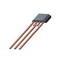
A1373LKB
Description
IC SENSOR HALL EFFECT PREC 3-SIP
Manufacturer
Allegro Microsystems Inc
Type
Bipolar or Unipolar, Programmabler
Datasheet
1.A1374LKB-T.pdf
(23 pages)
Specifications of A1373LKB
Sensing Range
1.75mV/G ~ 11.25mV/G
Voltage - Supply
4.5 V ~ 5.5 V
Current - Supply
10mA
Current - Output (max)
10mA
Output Type
Analog, Ratiometric
Features
High Precision
Operating Temperature
-40°C ~ 150°C
Package / Case
3-SIP
Magnetic Type
Unipolar
Operating Supply Voltage (min)
4.5V
Operating Supply Voltage (typ)
5V
Operating Supply Voltage (max)
5.5V
Output Current
10mA
Package Type
SIP
Pin Count
3
Mounting
Through Hole
Operating Temp Range
-40C to 150C
Operating Temperature Classification
Automotive
Lead Free Status / RoHS Status
Contains lead / RoHS non-compliant


A1373
A1374
INITIAL STATE
After system power-up, the programming logic is reset to a
known state. This is referred to as the Initial state. All the regis-
ters that have intact fuses are set to logic 0.
While in the Initial state, any V
ignored.
To enter the Mode Selection state, send one V
VOUT pin.
MODE SELECTION STATE
This state allows the selection of the programming mode:
• Try Value Mode. In this mode, the user provisionally downloads
• Blow Fuse Mode. In this mode, after downloading the settings, the
• Lock Device Mode. This mode is similar to Blow Fuse mode, except
To select a mode, increment through the register bitfields by
sending V
This register wraps by default. This means that sending addi-
tional VPL pulses traverses the register again.
Any V
To enter the Register Selection state, after sending a valid quan-
tity of V
REGISTER SELECTION STATE
This state allows the selection of the register containing the
bitfields to be programmed. Selecting the register corresponds to
selecting the parameter to be set. For bit codes, see the section
Programming Logic.
• QVO [V
• QVO Fine. Register for setting the value within the range set in the
• Sens. [Sensivity] Coarse. Register for setting the overall gain of the
settings to the device registers, without blowing the bits. The user
can increment through the codes of each parameter, and evaluate the
results of various code settings.
user can blow the fuses in specific registers.
that the fuse that is blown permanently prevents any further program-
ming of any bits in the device.
0 pulses – No effect
1 pulse – Try Value mode
2 pulses – Blow Fuse mode
3 pulses – Lock Device mode
ing dc point (2 bits)
QVO Coarse register (9 bits)
device (2 bits)
PH
PL
pulse sent before a V
OUT(Q)
PL
pulses, send one V
pulses on the VOUT pin, as follows:
and
] Coarse. Register for setting the range of the operat-
Programming Protocol and State Machine Description
PH
PL
PL
pulse on the VOUT pin.
pulse has no effect.
pulses on the VOUT pin are
PH
High Precision, Output Pin Programmable
pulse on the
• Sens. Fine. Register for setting the value within the range set in the
• [Sensitivity] TC Register. Register for setting the temperature coef-
• Clamp [V
• Polarity Bit. Register setting the polarity of the output (1 bit)
To select a register, increment through the register bitfields by
sending V
ming of registers should follow the order shown in item 7 in the
section Programming Guidelines, not the bitfield selection order
shown here. The bitfield selection order is:
This register wraps by default.
To enter the Bitfield Selection state, send one V
VOUT pin.
BITFIELD SELECTION STATE (Write Mode)
This state allows the selection of the individual bitfields to be
programmed, in the register selected in the Register Selection
state.
In Try Value mode, the total value of the bitfields selected incre-
ments by 1 with each V
eter being programmed changes with each additional pulse, so
measurements can be taken after each pulse to determine if the
desired result has been acquired.
In Blow Fuses mode, each bitfield to be blown must be selected
individually.
For bit codes and wrapping for these registers, see the section
Programming Logic.
To leave this state, send one V
current mode is Try Value, the bitfields remain set and the device
reverts to the Mode Selection state. If the current mode is Blow
Fuse, the selected bitfield fuse is blown, and the device reverts to
the Mode Selection state.
Sens. Coarse register (8 bits)
ficient for the device (5 bits).
the output (2 bits)
0 pulses – QVO Coarse register
1 pulse – QVO Fine register
2 pulses – Sens. Coarse register
3 pulses – Sense Fine register
4 pulses – TC Register register
5 pulses – Clamp Bit register
6 pulses – Polarity Bit register
Linear Hall Effect Sensor ICs
PL
OUTCLP
pulses on the VOUT pin. Note that the program-
] Bit. Register for setting the clamping voltage of
PL
pulse on the VOUT pin. The param-
115 Northeast Cutoff
1.508.853.5000; www.allegromicro.com
Allegro MicroSystems, Inc.
Worcester, Massachusetts 01615-0036 U.S.A.
PH
pulse on the VOUT pin. If the
PH
pulse on the
18
Related parts for A1373LKB
Image
Part Number
Description
Manufacturer
Datasheet
Request
R

Part Number:
Description:
IC, HALL EFFECT SENSOR, Linear, SOIC-8
Manufacturer:
Allegro Microsystems Inc
Datasheet:
Part Number:
Description:
IC, HALL EFFECT SENSOR, Linear, SOIC-8
Manufacturer:
Allegro Microsystems Inc
Datasheet:
Part Number:
Description:
IC, HALL EFFECT SENSOR, Linear, SOIC-8
Manufacturer:
Allegro Microsystems Inc
Datasheet:

Part Number:
Description:
IC SWITCH INTERFACE 2CHAN 8-SOIC
Manufacturer:
Allegro Microsystems Inc
Datasheet:

Part Number:
Description:
IC SMOKE DETECTOR ION 16-DIP
Manufacturer:
Allegro Microsystems Inc
Datasheet:
Part Number:
Description:
IC SMOKE DETECTOR ION 16-DIP
Manufacturer:
Allegro Microsystems Inc
Datasheet:
Part Number:
Description:
IC SMOKE DETECTOR ION 16-DIP
Manufacturer:
Allegro Microsystems Inc
Datasheet:
Part Number:
Description:
IC SMOKE DETECTOR PHOTO 16-DIP
Manufacturer:
Allegro Microsystems Inc
Datasheet:
Part Number:
Description:
IC SMOKE DETECTOR ION 16-DIP
Manufacturer:
Allegro Microsystems Inc
Datasheet:
Part Number:
Description:
IC SMOKE DETECTOR PHOTO 16-DIP
Manufacturer:
Allegro Microsystems Inc
Datasheet:
Part Number:
Description:
IC SMOKE DETECTOR PHOTO 16-DIP
Manufacturer:
Allegro Microsystems Inc
Datasheet:
Part Number:
Description:
IC SMOKE DETECTOR ION 16-DIP
Manufacturer:
Allegro Microsystems Inc
Datasheet:
Part Number:
Description:
IC SMOKE DETECTOR PHOTO 16-SOIC
Manufacturer:
Allegro Microsystems Inc
Datasheet:

Part Number:
Description:
IC LED DRIVER HIGH BRIGHT 16-QFN
Manufacturer:
Allegro Microsystems Inc
Datasheet:

Part Number:
Description:
IC LED DRIVER AUTOMOTIVE 8-SOIC
Manufacturer:
Allegro Microsystems Inc
Datasheet: