T1610000 Red Lion Controls, T1610000 Datasheet - Page 14
T1610000
Manufacturer Part Number
T1610000
Description
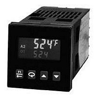
Process/Temperature Controller
Manufacturer
Red Lion Controls
Type
Temperaturer
Specifications of T1610000
Operating Temperature Max
50°C
Operating Temperature Min
0°C
Output Voltage Max
250VAC
Controller Input
Thermocouple Or RTD
Supply Voltage Max
250VAC
Mounting Type
Panel Mount
Brand/series
T16 Series
Contact Form
SPST
Dimensions
49.5mmW×49.5mmH×115.3mmD
Enclosure Rating
IP65
Input Type
RTD/Thermocouple
Ip Rating
IP65
Memory
EEPROM
Output Type
Relay
Power, Rating
8 VA
Primary Type
Controller
Special Features
EEPROM
Standards
cURus, CE
Termination
Screw
Voltage, Supply
85 to 250 VAC
Thermocouple Type
J, K, T, E, R, S, B, N, C And Linear MV
Rohs Compliant
Yes
Lead Free Status / RoHS Status
Lead free / RoHS Compliant


It is the total time for one on and one off period of the time proportioning
control output O1. With time proportional control, the percentage of power is
converted into an output on-time relative to the cycle time value set. (If the
controller calculates that 65% power is required and a cycle time of 10.0
seconds is set, the output will be on for 6.5 seconds and off for 3.5 seconds.)
For best control, a cycle time equal to one-tenth or less, of the natural period of
oscillation of the process is recommended. When using the Analog Output
signal for control, the Cycle Time setting has no effect. If the O1 output is not
being used, a cycle time of 0 can be entered to prevent the output and indicator
from cycling.
action (cooling), the output power will increase if the Process value is above the
Setpoint value. Programmed for reverse action (heating), the output power
decreases when the Process Value is above the Setpoint Value. For heat and cool
applications, this is typically set to reverse. This allows O1 or A1 (models with
Analog Output) to be used for heating, and A2/O2 to be used for cooling.
process disturbances or setpoint changes. Enter the safe output power limits for
the process. If Alarm 2 is selected for cooling, the range is from -100 to +100%.
At 0%, both O1 and O2 are off; at 100%, O1 is on; and at -100%, O2 is on.
When the controller is in Manual Control Mode, this limit does not apply.
7.2 MODULE 2 - O
CYCt
The Cycle Time is entered in seconds with one tenth of a second resolution.
OPAC
This determines the control action for the PID loop. Programmed for direct
OPLO
This parameter may be used to limit controller power at the lower end due to
OPHI
This parameter may be used to limit controller power at the upper end due to
rEv
100
2. 0
0
OUTPUT POWER LOWER LIMIT
OUTPUT POWER UPPER LIMIT
0. 0
drct
rEv
0
-100
0
-100
to
to
to
CONTROL ACTION
Reverse (heating)
100
100
250. 0
Direct (cooling)
to
to
CYCLE TIME
100
100
percent O1
percent O1
seconds
percent O1/O2
percent O1/O2
UTPUT
P
PARAMETER MENU
ARAMETERS
14
sensor failure. If Alarm 2 is not selected for cooling, the range is from 0% (O1
output full off) to 100% (O1 output full on). If A2 is selected for cooling, the
range is from -100 to +100%. At 0%, both O1 and O2 are off; at 100%, O1 is
on; and at -100%, O2 is on. The alarm outputs are upscale drive with an open
sensor, and downscale drive with a shorted sensor (RTD only), independent of
this setting. Manual Control overrides the sensor fail preset.
(filters) the calculated output power. Increasing the value increases the
dampening effect. Generally, dampening times in the range of one-twentieth to
one-fiftieth of the controller’s integral time (or process time constant) are
effective. Dampening times longer than these may cause controller instability
due to the added lag effect.
Proportional Band to 0.0%. The On/Off Control Hysteresis (balanced around
the setpoint) eliminates output chatter. In heat/cool applications, the control
hysteresis value affects both Output O1 and Output O2 control. It is suggested
to set the hysteresis band to Factory Setting prior to starting Auto-Tune. After
Auto-Tune, the hysteresis band has no effect on PID Control. On/Off Control
Hysteresis is illustrated in the On/Off Control Mode section.
dampening level under PID Control. This value allows customization of the PID
values that Auto-Tune will calculate. For the process to be controlled
aggressively (fastest process response with possible overshoot), set the Auto-
Tune Code to 0. For the process to be controlled conservatively (slowest
response with the least amount of overshoot), set this value to 2. If the Auto-Tune
Code is changed, Auto-Tune needs to be reinitiated for the changes to affect the
PID settings. For more information, see PID Tuning Explanations Section.
OPFL
This parameter sets the power level for the control outputs in the event of a
The Dampening Time, entered as a time constant in seconds, dampens
The controller can be placed in the On/Off Control Mode by setting the
tcod
Prior to starting Auto-Tune, this code should be set to achieve the necessary
OPdP
CHYS
(
0
0
0. 2
3
1
2
T16
P16
T16
P16
ON/OFF CONTROL HYSTERESIS
OUTPUT POWER DAMPENING
SENSOR FAIL POWER LEVEL
)
0
-100
0
to
fastest to
AUTO-TUNE CODE
0
100
1
to
to
to
100
250
percent O1
250
2
percent O1/O2
seconds
slowest
Related parts for T1610000
Image
Part Number
Description
Manufacturer
Datasheet
Request
R

Part Number:
Description:
Counter
Manufacturer:
Red Lion Controls
Datasheet:
Part Number:
Description:
Miniature Length Sensor
Manufacturer:
Red Lion Controls
Datasheet:
Part Number:
Description:
Model Lsc - Single Channel Output Length Sensor
Manufacturer:
Red Lion Controls
Datasheet: