SI-HG80DQD BANNER ENGINEERING, SI-HG80DQD Datasheet - Page 3
SI-HG80DQD
Manufacturer Part Number
SI-HG80DQD
Description
SWITCH, SAFETY INTERLOCK, 1NO/1NC, 3A
Manufacturer
BANNER ENGINEERING
Type
Interlockr
Datasheet
1.SI-HG80A.pdf
(8 pages)
Specifications of SI-HG80DQD
Contact Configuration
SPDT
Contact Voltage Ac Max
250V
Contact Voltage Dc Max
60V
Contact Current Ac Max
3A
Contact Current Dc Max
500mA
Switch Operation
ON-OFF
Actuator Type
Flexible
Current, Rating
3/0.5 AAC/ADC
Function
Safety
Ip Rating
IP67
Number Of Poles
1
Number Of Positions
2
Termination
Quick Connect
Voltage, Rating
250/60 VAC/VDC


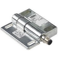
Figure 1. Hinge switch with set screw head
Do not use the switch as an end stop.
The operating angle of the switch must be
limited by outer end stops.
of the set screw after it is set, and before
using the switch.
If not, the safe activation of the switch can not
be ensured.
hazard point through an opened guard (or
any opening) before hazardous machine
motion has completely stopped. Please
reference OSHA CFR 1910.217 and ANSI
B11 standards (see page 2) for information
on determining safety distances and safe
opening sizes for your guarding devices.
Banner Engineering Corp. • Minneapolis, MN U.S.A.
www.bannerengineering.com • Tel: 763.544.3164
in place
CAUTION . . .
End Stops
CAUTION . . .
Set Screw Head
Shear off the hexagonal head
WARNING ...
It must not be possible for
personnel to reach any
Set Screw Head
Remove
All mounting hardware is supplied by the user. Fasteners must be of sufficient
strength to guard against breakage. Use of permanent fasteners or locking hardware
is recommended to prevent loosening or displacement of the actuator and the switch
body. The mounting holes in the switch body and the actuator accept M6 screws (see
dimension drawings, pages 6 and 7).
Ensure that excessive force is not exerted by the weight and swing of the guard, gate, or
door. (See specifications on page 6.)
Position blank hinges (if used) and the hinge switch(es) on the guard or gate while it is
in its fully closed and latched position. Verify that the axis of rotation is identical for all
hinges used. (Typically, this can be accomplished by using a straight edge along the
long flat edge to ensure the switch bodies are parallel.) After the mounting hardware is
secure, check the rotation of the guard or gate for misalignment and binding.
NOTE: A safety switch must be installed in a manner that discourages tampering or
Setting the Switch Point
1. Ensure that the hinge switches (and blind hinges, if used) are properly mounted and
2. Place the guard in its closed and latched position.
3. Tighten the hexagonal set screw head with a 13 mm open-ended wrench (rotate
4. Continue tightening until the set screw head shears completely off the switch. When
NOTE: Once the switch point is set, it can not be changed. Before proceeding, double-
that the guard or gate swings freely throughout its range of motion without binding. If
binding is noticed, repeat the mechanical installation procedures above.
clockwise when switch is mounted vertically and the nut is on top). See Figure 1.
the screwhead shears off, the switch point is set.
defeat.
check that the installation is correct and the resulting switching action is what is
expected.
Mechanical Installation
Hinge Switches –
SI-HG80 Series
P/N 46735 rev. B
Related parts for SI-HG80DQD
Image
Part Number
Description
Manufacturer
Datasheet
Request
R

Part Number:
Description:
PCB FUSE CARRIER AUTO TYPE 15A
Manufacturer:
Phoenix Contact
Datasheet:
Part Number:
Description:
PCB FUSE CARRIER AUTO TYPE 30A
Manufacturer:
Phoenix Contact
Datasheet:

Part Number:
Description:
Photoelectric Sensor
Manufacturer:
BANNER ENGINEERING
Datasheet:

Part Number:
Description:
Photoelectric Sensor
Manufacturer:
BANNER ENGINEERING
Datasheet:

Part Number:
Description:
LEDIR70XD4-XM-81039 MAX INTENS STROBE ONLY NO BANNER MARKS
Manufacturer:
BANNER ENGINEERING
Part Number:
Description:
M18SP6DL-72225 LABELED MOELLER NO BANNER MARKINGS BULK PACK
Manufacturer:
BANNER ENGINEERING
Part Number:
Description:
M18SP6DLQ-72226 LABLED MOELLER NO BANNER MARKINGS BULK PACK
Manufacturer:
BANNER ENGINEERING
Part Number:
Description:
M18SP6L-72223 LABELED MOELLER NO BANNER MARKINGS BULK PACK
Manufacturer:
BANNER ENGINEERING
Part Number:
Description:
Photoelectric Sensor
Manufacturer:
BANNER ENGINEERING
Datasheet:

Part Number:
Description:
Programmable Indicator Light
Manufacturer:
BANNER ENGINEERING
Datasheet:
Part Number:
Description:
INDICATOR LED PANEL 50MM GRN/RED/YEL 30V
Manufacturer:
BANNER ENGINEERING
Datasheet:
Part Number:
Description:
Programmable Indicator Light
Manufacturer:
BANNER ENGINEERING
Datasheet: