SI-HG80DQD BANNER ENGINEERING, SI-HG80DQD Datasheet - Page 4
SI-HG80DQD
Manufacturer Part Number
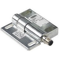
SI-HG80DQD
Description
SWITCH, SAFETY INTERLOCK, 1NO/1NC, 3A
Manufacturer
BANNER ENGINEERING
Type
Interlockr
Datasheet
1.SI-HG80A.pdf
(8 pages)
Specifications of SI-HG80DQD
Contact Configuration
SPDT
Contact Voltage Ac Max
250V
Contact Voltage Dc Max
60V
Contact Current Ac Max
3A
Contact Current Dc Max
500mA
Switch Operation
ON-OFF
Actuator Type
Flexible
Current, Rating
3/0.5 AAC/ADC
Function
Safety
Ip Rating
IP67
Number Of Poles
1
Number Of Positions
2
Termination
Quick Connect
Voltage, Rating
250/60 VAC/VDC


As illustrated in Figure 2, a normally-closed safety contact (i.e., a safety contact that is
closed when the actuator is engaged) from each of two safety switches per interlock
guard must connect to a 2-channel safety module or safety interface in order to achieve
a control reliable interface to the master stop control elements of a machine. Examples
of appropriate safety modules include 2-channel emergency stop (E-stop) safety modules
and gate monitor safety modules.
Two functions of the safety module or safety interface are:
1. to provide a means of monitoring the contacts of both safety switches for contact
2. to provide a reset routine after closing the guard and returning the safety switch
Use only the positively driven, normally closed safety contact (between pins 1 and 2) from
each switch for connection to the safety module. A typical use is to communicate with a
process controller. Refer to the installation instructions provided with the safety modules
for more information regarding the interface of the safety module to the machine stop
control elements.
Hinge Switches –
failure, and to prevent the machine from restarting if either switch fails; and
contacts to their closed position. This prevents the controlled machinery from restarting
by simply closing the guard. This necessary reset function is required by ANSI B11 and
NFPA 79 machine safety standards.
P/N 46735 rev. B
Electrical Connection
SI-HG80 Series
Banner Engineering Corp. • Minneapolis, MN U.S.A.
www.bannerengineering.com • Tel: 763.544.3164
Figure . Connect two redundant safety
NOTE: Refer to the installation instructions
Input Channel
used for each interlock guard to achieve
control reliability or Safety Category (per
ISO 189-1, EN 95-1) of a machine stop
circuit. Use of only one safety switch per
interlock guard is not recommended.
In addition, normally-closed safety contacts
from each of the two safety switches should
be connected to the two separate inputs of a
2-channel safety module or safety interface,
as illustrated in Figure 6. This is required to
provide monitoring for safety switch contact
failure, and to provide the necessary reset
routine, as required by IEC 60204-1 and
NFPA 79 machine safety standards.
Monitoring multiple guards with a series
connection of multiple safety interlock
switches is not a Safety Category
Application (per ISO 189-1, EN 95-1).
A single failure may be masked or not
detected at all. When such a configuration
is used, procedures must be performed
regularly to verify proper operation of each
switch.
2-channel Gate Monitor Module, etc.)
Safety Switch
2
#1
provided with the safety module for
information regarding the interface of the
safety module to the machine stop control
elements.
#1
(2-channel E-stop Module
2-channel Safety Module
switches per interlock guard to an
appropriate -channel input safety
module.
1
WARNING . . .
Connection of Safety
Interlock Switches
CAUTION . . .
Electrical Installation
Two safety switches must be
Safety Switch
2
Input Channel
#2
#2
1
Series
Single gate
or guard
Related parts for SI-HG80DQD
Image
Part Number
Description
Manufacturer
Datasheet
Request
R

Part Number:
Description:
PCB FUSE CARRIER AUTO TYPE 15A
Manufacturer:
Phoenix Contact
Datasheet:
Part Number:
Description:
PCB FUSE CARRIER AUTO TYPE 30A
Manufacturer:
Phoenix Contact
Datasheet:

Part Number:
Description:
Photoelectric Sensor
Manufacturer:
BANNER ENGINEERING
Datasheet:

Part Number:
Description:
Photoelectric Sensor
Manufacturer:
BANNER ENGINEERING
Datasheet:

Part Number:
Description:
LEDIR70XD4-XM-81039 MAX INTENS STROBE ONLY NO BANNER MARKS
Manufacturer:
BANNER ENGINEERING
Part Number:
Description:
M18SP6DL-72225 LABELED MOELLER NO BANNER MARKINGS BULK PACK
Manufacturer:
BANNER ENGINEERING
Part Number:
Description:
M18SP6DLQ-72226 LABLED MOELLER NO BANNER MARKINGS BULK PACK
Manufacturer:
BANNER ENGINEERING
Part Number:
Description:
M18SP6L-72223 LABELED MOELLER NO BANNER MARKINGS BULK PACK
Manufacturer:
BANNER ENGINEERING
Part Number:
Description:
Photoelectric Sensor
Manufacturer:
BANNER ENGINEERING
Datasheet:

Part Number:
Description:
Programmable Indicator Light
Manufacturer:
BANNER ENGINEERING
Datasheet:
Part Number:
Description:
INDICATOR LED PANEL 50MM GRN/RED/YEL 30V
Manufacturer:
BANNER ENGINEERING
Datasheet:
Part Number:
Description:
Programmable Indicator Light
Manufacturer:
BANNER ENGINEERING
Datasheet: