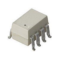
ACPL-J313-300E Avago Technologies US Inc., ACPL-J313-300E Datasheet - Page 11

ACPL-J313-300E
Manufacturer Part Number
ACPL-J313-300E
Description
Gate Drive Optocoupler,SMD+LF
Manufacturer
Avago Technologies US Inc.
Datasheet
1.ACPL-3130-500E.pdf
(20 pages)
Specifications of ACPL-J313-300E
Voltage - Isolation
3750Vrms
Number Of Channels
1, Unidirectional
Current - Output / Channel
2.5A
Propagation Delay High - Low @ If
300ns @ 10mA ~ 16mA
Current - Dc Forward (if)
25mA
Input Type
DC
Output Type
Push-Pull, Totem-Pole
Mounting Type
Surface Mount
Package / Case
8-SMD Gull Wing
Number Of Elements
1
Forward Voltage
1.95V
Forward Current
25mA
Isolation Voltage
3750Vrms
Package Type
PDIP SMD
Operating Temp Range
-40C to 100C
Power Dissipation
295mW
Propagation Delay Time
500ns
Pin Count
8
Mounting
Surface Mount
Reverse Breakdown Voltage
5V
Operating Temperature Classification
Industrial
Lead Free Status / RoHS Status
Lead free / RoHS Compliant
Lead Free Status / RoHS Status
Lead free / RoHS Compliant
Notes:
1. Derate linearly above 70° C free-air temperature at a rate of 0.3 mA/°C.
2. Maximum pulse width = 10 µs, maximum duty cycle = 0.2%. This value is intended to allow for component tolerances for designs with I
3. Derate linearly above 70° C free-air temperature at a rate of 4.8 mW/°C.
4. Derate linearly above 70° C free-air temperature at a rate of 5.4 mW/°C. The maximum LED junction temperature should not exceed 125°C.
5. Maximum pulse width = 50 µs, maximum duty cycle = 0.5%.
6. In this test V
7. Maximum pulse width = 1 ms, maximum duty cycle = 20%.
8. In accordance with UL1577, each optocoupler is proof tested by applying an insulation test voltage �� 4500 V
9. In accordance with UL1577, each optocoupler is proof tested by applying an insulation test voltage �� 4500 V
10. In accordance with UL1577, each optocoupler is proof tested by applying an insulation test voltage �� 6000 V
11. Device considered a two-terminal device: pins 1, 2, 3, and 4 shorted together and pins 5, 6, 7, and 8 shorted together.
12. The difference between t
13. Pins 1 and 4 need to be connected to LED common.
14. Common mode transient immunity in the high state is the maximum tolerable dV
15. Common mode transient immunity in a low state is the maximum tolerable dV
16. This load condition approximates the gate load of a 1200 V/75A IGBT.
17. Pulse Width Distortion (PWD) is defined as |t
Figure 1. V
Figure 4. V
0.25
0.20
0.15
0.10
0.05
minimum = 2.0 A. See Applications section for additional details on limiting I
current limit, I
current limit, I
current limit, I
will remain in the high state (i.e., V
will remain in a low state (i.e., V
-1
-2
-3
-4
0
0
-40
-40
OH
OL
-20
-20
vs. Temperature.
I
I
V
V
vs. Temperature.
T
F
OUT
T
CC
EE
A
V
I
V
V
OUT
= 7 to 16 mA
A
OH
F
CC
EE
- TEMPERATURE - °C
- TEMPERATURE - °C
0
= 0 V
(OFF) = -3.0 TO 0.8 V
I-O
I-O
I-O
= 15 to 30 V
= -100 mA
0
is measured with a dc load current. When driving capacitive loads V
= 0 V
= 15 TO 30 V
= 100 mA
�� 5 µA).
�� 5 µA).
�� 5 µA).
�� 5 µA).
�� 5 µA).
�� 5 µA).
2 0
5 µA).
5 µA).
5 µA).
2 0
40
40
PHL
and t
60
60
O
< 1.0 V).
80
PLH
O
80
> 15.0 V).
between any two ACPL-3130, ACPL-J313 or ACNW3130 parts under the same test condition.
100
100
PHL
Figure 2. I
Figure 5. I
- t
PLH
2.0
1.8
1.6
1.4
1.2
1.0
4
3
2
1
0
| for any given device.
-40
-40
OH
OL
-20
-20
vs. Temperature.
vs. Temperature.
I
V
V
V
T
T
F
V
V
V
V
OUT
CC
EE
A
A
F
OUT
CC
EE
= 7 to 16 mA
- TEMPERATURE - °C
- TEMPERATURE - °C
(OFF) = -3.0 TO 0.8 V
0
= 0 V
0
= 15 to 30 V
= 0 V
= 15 TO 30 V
= (V
= 2.5 V
2 0
2 0
CC
- 4 V)
40
40
OH
peak.
60
60
CM
CM
/dt of the common mode pulse, V
OH
/dt of the common mode pulse, V
80
80
will approach V
100
100
Figure 3. V
Figure 6. V
�� 4500 V
�� 4500 V
�� 6000 V
CC
4500 V
4500 V
6000 V
-1
-2
-3
-4
-5
-6
as I
4
3
2
1
0
0
0
I
I
OH
OL
OH
OH
OL
I
V
V
F
approaches zero amps.
rms
rms
rms
CC
EE
- OUTPUT LOW CURRENT - A
= 7 to 16 mA
- OUTPUT HIGH CURRENT - A
vs. I
0.5
vs. I
0.5
for 1 second (leakage detection
for 1 second (leakage detection
for 1 second (leakage detection
= 0 V
= 15 to 30 V
V
V
V
F(OFF)
CC
EE
OL
OH
CM
.
CM
.
= 0 V
= 15 to 30 V
1.0
1.0
, to assure that the output
, to assure that the output
= -3.0 to 0.8 V
1.5
1.5
100 ° C
25 ° C
-40 ° C
2.0
2.0
100 ° C
25 ° C
-40 ° C
O peak
2.5
2.5


