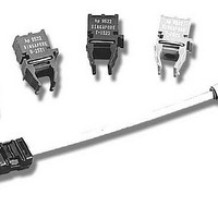
HFBR-0564 Avago Technologies US Inc., HFBR-0564 Datasheet - Page 10

HFBR-0564
Manufacturer Part Number
HFBR-0564
Description
Fiber Optics, Evaluation Kit
Manufacturer
Avago Technologies US Inc.
Datasheet
1.HFBR-0562.pdf
(14 pages)
Specifications of HFBR-0564
Silicon Manufacturer
Avago
Silicon Core Number
HFBR-591xE
Kit Application Type
Communication & Networking
Application Sub Type
MT-RJ Gigabit Ethernet Transceiver
Main Purpose
Interface, Ethernet
Embedded
No
Utilized Ic / Part
HFCT-591xE, HFBR-591xE
Primary Attributes
MT-RJ Gigabit, Multimode and Singlemode Applications
Secondary Attributes
MT-RJ Fiber Connector Interface
Operating Voltage
3.3 V
Description/function
Fiber Optic Kit
Lead Free Status / RoHS Status
Lead free / RoHS Compliant
For Use With/related Products
HFBR-591x, HFCT-591
Lead Free Status / RoHS Status
Lead free / RoHS Compliant, Contains lead / RoHS non-compliant
10
7. If possible, distribute V
8. Place V
9. Use high-quality, high-frequency
EMI Radiation/Susceptibility
Radiated emissions for the HFBR-
591xE and HFCT-591xE have been
tested successfully in several en-
vironments. Data sheet values will
normally describe emissions be-
havior in a worst-case, open air, un-
shielded environment. While this
number is important for system
designers in terms of emissions
levels inside a system, Avago rec-
ognizes that the performance of
most interest to our customers is
the emissions levels which could be
expected to radiate from a typical
system chassis. In their application,
SFF transceivers are intended for
use inside an enclosed system, pro-
truding through the specified panel
opening at the specified protrusion
depth. (See the Board Layout Con-
siderations section for appropriate
dimensions and layout informa-
tion). For more detailed information
on fiber optic and system EMI and
testing, see also AN 1166.
Given that the emissions from one
transceiver is L (dBµV/m) we can the-
oretically scale multiple transceiver
via a plane rather than by traces.
This helps minimize the inductive
effect of traces on the switching
logic currents supplied from V
as close as possible to the V
locations that require bypassing.
surface-mount components for
best
mance. Surface mount coil in-
ductors should have < 0.7 W
series resistance and a high
self-resonant frequency. Ferrite
beads can be substituted for coil
inductors if the power supply
noise is fairly quiet. The 0.1 µF
capacitors should be monolithic,
ceramic type capacitors and
the 10 µF capacitor should be a
tantalum.
high-frequency
CC
bypass capacitors
CC
perfor-
power
CC
CC
.
performance
where N is the number of trans-
ceivers. For example, if we have a
reading of 20 dBµV/m for a single
transceiver, we would theoretically
expect for 100 of the same transceiv-
ers, an increase of 10log(N), or 20 dB,
to 40 dBµV/m. We have measured
some systems which follow this
curve quite closely. Repeatability of
the measurement setup and repeat-
ability in reassembling the system
for different configurations can have
a large impact on actual results.
The radiation patterns produced by
dense arrays of SFF transceivers can
be very complex and difficult to ac-
curately characterize or predict. The
10 log(N) relationship should only
be used as a rough guideline.
The evaluation board used for EMI
testing contains just one SFF trans-
ceiver and the specified termina-
tions. Layout is per the recommen-
dations in this application note with
the exception of mounting holes,
which are slightly larger to accom-
modate pin sockets that allow easy
installation and removal of the trans-
ceiver. For testing, 1010 optical data
running at 1250 Mb/s is fed to the
Rx side. Rx signals are looped back
directly to Tx electrically through 50
W stripline transmission lines.
For simulated chassis measurements,
the evaluation board is screwed into
a small, RF tight metal box with just
the recommended panel opening
for the transceiver port. A +3.3 V DC
bias is brought in through the wall
using a bulkhead connector mated
to an SMA semi-rigid cable. Open
air measurements are with the lid
removed, exposing the entire top
surface of the evaluation board and
transceiver. The transceiver and RF
box were manipulated 360° over all
three axes to determine maximum
available emissions.
EMI response for both multimode
and single mode transceivers was
measured under open air and
using
10log(N)+L,
simulated
Figures 11 to 14 show the worst EMI
response when measured from 30
MHz to 7 GHz.
Clearly, the transceiver passes FCC-B
under open air conditions, indicat-
ing that it should be feasible from
an emissions standpoint to use
the parts in quantities of over 100.
Simulated chassis measurements
are at or near the measurement
floor. Indicating that with careful
enclosure and PCB layout design,
high port density may be possible.
Careful attention must be paid to
the locations of high-speed clocks
or gigabit circuitry with respect to
these apertures. While our meas-
urements and experiences do not
indicate any specific transceiver
emissions issues, Avago recognizes
that the transceiver aperture is often
the weakest link in system enclosure
integrity. Avago has designed the
modules to minimize emissions and,
if necessary, contain the internal
system emissions by shielding the
aperture.
To that end, our gigabit MT-RJ
transceivers (HFCT-591xE & HFBR-
591xE) have “metal nose” shields
that provide a convenient chassis
ground connection to the nose of
the transceiver. This metal nose
shield improves the EMI per-
formance of the transceiver and
improves system EMI performance
by minimizing the MT-RJ aperture.
Localized shielding is also improved
by connecting metal housing solder
pins to signal ground on the PCB.
Though not obvious by inspection,
the nose clip and metal housing are
electrically separated for users that
do not wish to directly tie chassis
and signal grounds together. The
recommended transceiver position,
PCB layout and panel opening for
both the HFBR-591xE and HFCT-
591xE are the same, making them
physically compatible.
chassis
conditions.


