HFBR-0564 Avago Technologies US Inc., HFBR-0564 Datasheet - Page 6
HFBR-0564
Manufacturer Part Number
HFBR-0564
Description
Fiber Optics, Evaluation Kit
Manufacturer
Avago Technologies US Inc.
Datasheet
1.HFBR-0562.pdf
(14 pages)
Specifications of HFBR-0564
Silicon Manufacturer
Avago
Silicon Core Number
HFBR-591xE
Kit Application Type
Communication & Networking
Application Sub Type
MT-RJ Gigabit Ethernet Transceiver
Main Purpose
Interface, Ethernet
Embedded
No
Utilized Ic / Part
HFCT-591xE, HFBR-591xE
Primary Attributes
MT-RJ Gigabit, Multimode and Singlemode Applications
Secondary Attributes
MT-RJ Fiber Connector Interface
Operating Voltage
3.3 V
Description/function
Fiber Optic Kit
Lead Free Status / RoHS Status
Lead free / RoHS Compliant
For Use With/related Products
HFBR-591x, HFCT-591
Lead Free Status / RoHS Status
Lead free / RoHS Compliant, Contains lead / RoHS non-compliant


6
Board Layout Considerations
The partners in the MT-RJ alliance
have agreed that all SFF transceiver
products will have the same physical
PCB footprint and connector panel
opening as documented in the
Multi-Source Agreement (MSA). The
MSA does not define all SFF physical
parameters, such as the overall
length, in order to give the partners
latitude in their designs. For this
reason, exactly what parameters
are defined by the MSA will be em-
phasized in the text reviewing the
Avago SFF dimensions. Note that the
MSA does not require shield ground
tabs on SFF products even though
the MSA includes ground pads on
the recommended PCB layout. The
shield grounding differences in the
various Avago SFF products will be
discussed during the presentation
of both the PCB layout and panel
opening drawings. Also described
are elements not controlled by
the MSA such as the SFF housing
material and color.
Shown in Figure 6 is the multimode
2 x 5 SFF 1.25 Gb: HFBR-5912E trans-
ceiver. The metal housing includes
ground tabs that are connected
to signal ground via the recom-
mended PCB layout. The metal nose
shield over the MT-RJ connector is
connected to chassis ground via the
spring contact fingers. The two front
standoffs are un-metallized. The two
rear standoffs are metallized and
connected to signal ground. The
metal nose shield and metal housing
are electrically isolated from each
other.
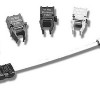
Shown in Figure 7 is the single mode
2 x 5 SFF 1.25 Gb/s HFCT-5912E trans-
ceiver. Similar to the HFBR-5912E,
these transceivers also have ground
tabs on the metal housing shield,
spring contact fingers on the metal
nose shield and electrical isolation
between these shields. Ground tabs
must be connected to signal ground
for optimum performance of the
transceiver. The two front standoffs
are metallized and at chassis ground.
The two rear standoffs are at signal
ground.
Figure 7. HFCT-5912E 2 x 5 1.25 Gb/s single mode SFF
Figure 6. HFBR-5912E 2 x 5 1.25 Gb multimode SFF
Related parts for HFBR-0564
Image
Part Number
Description
Manufacturer
Datasheet
Request
R

Part Number:
Description:
Fiber Optic Transmitters, Receivers, Transceivers 1300nm 155MBd 16-pin DIP ST Rx
Manufacturer:
Avago Technologies US Inc.

Part Number:
Description:
FIBER OPTIC TX 125 MBD 650N
Manufacturer:
Avago Technologies US Inc.
Datasheet:

Part Number:
Description:
Fiber Optic Evaluation Kit
Manufacturer:
Avago Technologies US Inc.
Datasheet:

Part Number:
Description:
RECEIVER FIBER OPTIC ST 266MBD
Manufacturer:
Avago Technologies US Inc.
Datasheet:

Part Number:
Description:
RCVR OPT HI SPEED VERS LINK HORZ
Manufacturer:
Avago Technologies US Inc.
Datasheet:

Part Number:
Description:
RCVR OPT HI SPEED VERS LINK VERT
Manufacturer:
Avago Technologies US Inc.
Datasheet:

Part Number:
Description:
TXRX OPTICAL 850NM VCSEL MT-RJ
Manufacturer:
Avago Technologies US Inc.
Datasheet:

Part Number:
Description:
TXRX MM SFP LC CONN BAIL DELATCH
Manufacturer:
Avago Technologies US Inc.
Datasheet:

Part Number:
Description:
TXRX MMF SFP GBE/FC BAIL DELATCH
Manufacturer:
Avago Technologies US Inc.
Datasheet:

Part Number:
Description:
XMITTER FIBER OPTIC 266MBD ST
Manufacturer:
Avago Technologies US Inc.
Datasheet:

Part Number:
Description:
OPTOCOUPLER GATE DRV 2A 16-SOIC
Manufacturer:
Avago Technologies US Inc.
Datasheet:
Part Number:
Description:
OPTOCOUPLER 2CH 2.5A 16-SOIC
Manufacturer:
Avago Technologies US Inc.
Datasheet:

Part Number:
Description:
OPTOCOUPLER GATE DRV 0.4A 16SOIC
Manufacturer:
Avago Technologies US Inc.
Datasheet:

Part Number:
Description:
OPTOCOUPLER 2.0A 250KHZ 8-DIP
Manufacturer:
Avago Technologies US Inc.
Datasheet:

Part Number:
Description:
OPTOCOUPLER 2.0A 250KHZ GW 8-SMD
Manufacturer:
Avago Technologies US Inc.
Datasheet: