702560 Spectrum Digital Inc, 702560 Datasheet - Page 23
702560
Manufacturer Part Number
702560
Description
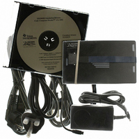
XDS560R USB JTAG Emulator With 20 Pin CTI JTAG Header
Manufacturer
Spectrum Digital Inc
Type
USB JTAG Emulatorr
Specifications of 702560
Contents
Board, Cable
Ic Product Type
USB JTAG Emulator
Kit Contents
XDS560R USB JTAG Emulator With CTI JTAG Header, CDROM With Drivers, USB Cable
Lead Free Status / RoHS Status
Lead free / RoHS Compliant
For Use With/related Products
TI DSPs and JTAG Microcontrollers
Lead Free Status / RoHS Status
Lead free / RoHS Compliant


3.3 XDS560R Emulator Cable Pod Logic
Figure 3-3 shows a portion of the XDS560R emulator cable pod. The following items
are characteristics of the XDS560R pod:
❏
❏
❏
❏
❏
❏
❏
❏
❏
❏
❏
EMU0/EMU1 is set to 1/2 of the TVD signal. For TVD voltages greater than 3.3 V, the
The TCK signal is AC termination on the return side of the TCK (TCK_RET). The
termination voltage is set to 1/2 of the TVD voltage to minimize loading effects.
10 KW resistor pulled up to the same voltage as set by TVD voltage.
trigger level is set to approximately 1.65 V.
signal, but can be generated from the falling edge of TCK_RET to be in accordance
with the IEEE 1149.1 bus slave device timing rules.
500 KHz to 50 MHz, but the operation is limited by timing of various signals and the
target devices. Note: All timing for the pod and emulator are from the TCK_RET
signal, therefore a user may provide their own test clock (TCK).
TVD signal is reduced by more than one third of its reset voltage.
ensure that the target inputs are at a set level given that the outputs from the
XDS560R pod are Hi-Z after a power failure or disconnect.
used to detect if the target pod is connected to a target board. Pin 4 on the user
target board must be connected to ground.
signal on the target board. The target board designer may use this pin 6 as an
optional Host Disconnect (HDIS) signal. This signal could be used within the target
board to detect if the JTAG emulator cable/pod header is connected.
The TDO signal from the slave device is terminated at the pod of the cable with a
The trigger level for high-to-low and low-to-high transition for TDO, TCK_RET, and
The pod provides a programmable (TCK) test clock source. The range of this TCK is
Signals TCK, TMS, TDI, and TRST have a 100 KW pull-down resistor. This is to
Pin 4 of the emulation header is the Target Disconnect (TDIS) signal. This signal is
The impedance of the emulation pod cable is 50 ohms.
Design Note: Pin 6 of the target emulation header is normally connected to a ground
Signals TMS, TDI and TRST are series terminated to reduce signal reflections.
The TCK signal output has a medium-current drive capability of 24 mA I
Signals TMS and TDI, by default, are generated on the rising-edge of the TCK_RET
All output signals from the pod are Hi-Z, whenever the pod power is turned on or
Spectrum Digital, Inc
OL
/I
OH
.
3-5
Related parts for 702560
Image
Part Number
Description
Manufacturer
Datasheet
Request
R

Part Number:
Description:
XDS560R Target Adapter Cable For 14 Pin JTAG Header
Manufacturer:
Spectrum Digital Inc
Datasheet:

Part Number:
Description:
MODULE EVAL FOR DM355
Manufacturer:
Spectrum Digital Inc
Datasheet:
Part Number:
Description:
DMC550 Digital Motor Controller For EZdsps
Manufacturer:
Spectrum Digital Inc
Part Number:
Description:
DMC1500 Digital Motor Controller For Switch Reluctance Motors
Manufacturer:
Spectrum Digital Inc
Part Number:
Description:
DMC1500 Digital Motor Controller For AC Induction/DC Brushless Motors
Manufacturer:
Spectrum Digital Inc
Datasheet:
Part Number:
Description:
TMS320DM357 Digital Video Evaluation Module 270 MHz TMS320DM357
Manufacturer:
Spectrum Digital Inc
Part Number:
Description:
EVM TMS320DM6467 Digital Video Development Platform
Manufacturer:
Spectrum Digital Inc


Part Number:
Description:
KIT STARTER DSP FOR C6416T
Manufacturer:
Spectrum Digital Inc
Datasheet:

Part Number:
Description:
CODE COMPOSR STUDIO EZDSP F28335
Manufacturer:
Spectrum Digital Inc
Datasheet:

Part Number:
Description:
EMULATOR C2000 SRS XDS510LC JTAG
Manufacturer:
Spectrum Digital Inc
Datasheet:

Part Number:
Description:
EMULATOR XDS510 USB JTAG 14PIN
Manufacturer:
Spectrum Digital Inc
Datasheet:

Part Number:
Description:
EMULATOR XDS510 USB PLUS W/CABLE
Manufacturer:
Spectrum Digital Inc
Datasheet:

Part Number:
Description:
EMULATOR XDS560R USB JTAG 14PIN
Manufacturer:
Spectrum Digital Inc
Datasheet: