702560 Spectrum Digital Inc, 702560 Datasheet - Page 25
702560
Manufacturer Part Number
702560
Description
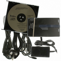
XDS560R USB JTAG Emulator With 20 Pin CTI JTAG Header
Manufacturer
Spectrum Digital Inc
Type
USB JTAG Emulatorr
Specifications of 702560
Contents
Board, Cable
Ic Product Type
USB JTAG Emulator
Kit Contents
XDS560R USB JTAG Emulator With CTI JTAG Header, CDROM With Drivers, USB Cable
Lead Free Status / RoHS Status
Lead free / RoHS Compliant
For Use With/related Products
TI DSPs and JTAG Microcontrollers
Lead Free Status / RoHS Status
Lead free / RoHS Compliant


3.4 XDS560R Emulator Cable Pod Signal Timing
No
1
2
3
4
5
6
t
t
t
t
T
T
c (T C K )
w( T CKH )
w( T CKL )
pd( T M S - T DI )
s u ( T D O )
hd (TD O )
Reference
Figure 3-4 shows the default timing waveforms for the XDS560R emulator cable pod.
The table below defines the timing parameters. These timing parameters are calculated
from values specified in the standard data sheets for the emulator and cable pod and
are for reference only.
The presented timing parameters are calculated for the end of the 14-pin target cable
header. Texas Instruments does not test or guarantee these timings.
The XDS560 emulator cable pod uses TCK_RET as its clock source for internal
synchronization. TCK is provided as an optional target system test-clock source.
Note: The delay timing for TMS/TDI valid is calculated for the default rising edge
TCK_RET. The delay time for TMS/TDI valid for a falling edge TCK_RET
configuration is vary similar.
TCK_RET
TMS/TDI
Table 2: Emulator Pod Timing Parameters
TDO
Cycle time, TCK_RET
Pulse duration, TCK_RET high
Pulse duration, TCK_RET low
Delay time, TMS/TDI valid from TCK_RET high
Setup time, TDO valid before TCK_RET high
Hold time, TDO valid after TCK_RET high
Figure 3-4, Emulator Pod Timings
2
Description
4
1
3
5
Spectrum Digital, Inc
6
Min
2.5
20
10
10
18
0
Max
31
Units
ns
ns
ns
ns
ns
ns
3-7
Related parts for 702560
Image
Part Number
Description
Manufacturer
Datasheet
Request
R

Part Number:
Description:
XDS560R Target Adapter Cable For 14 Pin JTAG Header
Manufacturer:
Spectrum Digital Inc
Datasheet:

Part Number:
Description:
MODULE EVAL FOR DM355
Manufacturer:
Spectrum Digital Inc
Datasheet:
Part Number:
Description:
DMC550 Digital Motor Controller For EZdsps
Manufacturer:
Spectrum Digital Inc
Part Number:
Description:
DMC1500 Digital Motor Controller For Switch Reluctance Motors
Manufacturer:
Spectrum Digital Inc
Part Number:
Description:
DMC1500 Digital Motor Controller For AC Induction/DC Brushless Motors
Manufacturer:
Spectrum Digital Inc
Datasheet:
Part Number:
Description:
TMS320DM357 Digital Video Evaluation Module 270 MHz TMS320DM357
Manufacturer:
Spectrum Digital Inc
Part Number:
Description:
EVM TMS320DM6467 Digital Video Development Platform
Manufacturer:
Spectrum Digital Inc


Part Number:
Description:
KIT STARTER DSP FOR C6416T
Manufacturer:
Spectrum Digital Inc
Datasheet:

Part Number:
Description:
CODE COMPOSR STUDIO EZDSP F28335
Manufacturer:
Spectrum Digital Inc
Datasheet:

Part Number:
Description:
EMULATOR C2000 SRS XDS510LC JTAG
Manufacturer:
Spectrum Digital Inc
Datasheet:

Part Number:
Description:
EMULATOR XDS510 USB JTAG 14PIN
Manufacturer:
Spectrum Digital Inc
Datasheet:

Part Number:
Description:
EMULATOR XDS510 USB PLUS W/CABLE
Manufacturer:
Spectrum Digital Inc
Datasheet:

Part Number:
Description:
EMULATOR XDS560R USB JTAG 14PIN
Manufacturer:
Spectrum Digital Inc
Datasheet: